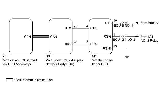
DTC B2779 Engine Starter Communication Malfunction |
| DTC Code | DTC Detection Condition | Trouble Area |
| B2779 | Either of the following conditions is met:
|
|
| 1.CHECK DTC OUTPUT |
Clear the DTC (Click here).
Perform the remote engine start operation.
Check for DTCs.
|
| ||||
| OK | |
 |
| 2.READ VALUE USING TECHSTREAM |
Turn the engine switch off.
Connect the Techstream to the DLC3.
Turn the engine switch on (IG).
Turn the Techstream on.
Enter the following menus: Body Electrical / Smart Key / Data List.
According to the display on the Techstream, read the Data List.
| Tester Display | Measurement Item/Range | Normal Condition | Diagnostic Note |
| Wireless C Code | Registration status between remote engine starter ECU and certification ECU (smart key ECU assembly)/No Regd or Regd | No Regd: ID not registered between remote engine starter ECU and certification ECU (smart key ECU assembly) Regd: ID registered between remote engine starter ECU and certification ECU (smart key ECU assembly) | - |
| Result | Proceed to |
| "No Regd" appears on the Techstream screen | A |
| "Regd" appears on the Techstream screen | B |
|
| ||||
| A | |
|
| 3.REGISTER REMOTE ENGINE STARTER ID |
Register the remote engine starter ID (Click here).
| NEXT | |
|
| 4.CHECK DTC OUTPUT |
Clear the DTC (Click here).
Perform the remote engine start operation.
Check for DTCs.
|
| ||||
| OK | ||
 | ||
| ||
| 5.CHECK HARNESS AND CONNECTOR (REMOTE ENGINE STARTER ECU - BATTERY AND BODY GROUND) |
Disconnect the I141 remote engine starter ECU connector.
Measure the voltage and resistance according to the value(s) in the table below.
| Tester Connection | Condition | Specified Condition |
| I141-10 (R+B) - Body ground | Always | 11 to 14 V |
| I141-1 (RSIG) - Body ground | Engine switch on (IG) | 11 to 14 V |
| I141-1 (RSIG) - Body ground | Engine switch off | Below 1 V |
| Tester Connection | Condition | Specified Condition |
| I141-19 (RGN1) - Body ground | Always | Below 1 Ω |
|
| ||||
| OK | |
|
| 6.CHECK HARNESS AND CONNECTOR (MAIN BODY ECU (MULTIPLEX NETWORK BODY ECU) - REMOTE ENGINE STARTER ECU) |
Disconnect the I13 main body ECU (multiplex network body ECU) connector.
Measure the resistance according to the value(s) in the table below.
| Tester Connection | Condition | Specified Condition |
| I13-25 (BTX) - I141-4 (BTX) | Always | Below 1 Ω |
| I13-26 (BRX) - I141-3 (BRX) | Always | Below 1 Ω |
| I13-25 (BTX) - Body ground | Always | 10 kΩ or higher |
| I13-26 (BRX) - Body ground | Always | 10 kΩ or higher |
|
| ||||
| OK | |
|
| 7.REPLACE REMOTE ENGINE STARTER ECU |
Temporarily replace the remote engine starter ECU with a new one (Click here).
| NEXT | |
|
| 8.REGISTER REMOTE ENGINE STARTER ID |
Register the remote engine starter ID (Click here).
| NEXT | |
|
| 9.CHECK DTC OUTPUT |
Clear the DTC (Click here).
Perform the remote engine start operation.
Check for DTCs.
|
| ||||
| OK | ||
| ||
| ||
| 10.REPLACE MAIN BODY ECU (MULTIPLEX NETWORK BODY ECU) |
Temporarily replace the main body ECU (multiplex network body ECU) with a new one (Click here).
| NEXT | |
|
| 11.CHECK DTC OUTPUT |
Clear the DTC (Click here).
Perform the remote engine start operation.
Check for DTCs.
|
| ||||
| OK | ||
| ||
| ||

