2AR-FE ENGINE MECHANICAL ENGINE UNIT INSTALLATION
CAUTION / NOTICE / HINT
- HINT:
-
Perform inspection after repair after replacing the engine assembly.
-
Click hereEngine / Hybrid System>2AR-FE (ENGINE CONTROL)>SFI SYSTEM>INITIALIZATION
PROCEDURE

 19500
1.INSTALL IGNITION COIL ASSEMBLY
89422
2.INSTALL ENGINE COOLANT TEMPERATURE SENSOR
83530
3.INSTALL ENGINE OIL PRESSURE SWITCH ASSEMBLY
89615
4.INSTALL KNOCK CONTROL SENSOR
82219A
5.INSTALL SENSOR WIRE
Install the sensor wire to the cylinder block sub-assembly with the bolt.
- Torque:
- 21 N*m (214 kgf*cm, 15 ft.*lbf)
Connect the knock control sensor connector.
17111
6.INSTALL INTAKE MANIFOLD
23250
7.INSTALL FUEL INJECTOR ASSEMBLY
23291
8.INSTALL INJECTOR VIBRATION INSULATOR
23891
9.INSTALL FUEL DELIVERY SPACER
23814B
10.INSTALL FUEL DELIVERY PIPE
12262
11.CONNECT NO. 2 VENTILATION HOSE
17650
12.INSTALL VACUUM SWITCHING VALVE ASSEMBLY (for ACIS)
13.INSTALL WATER BY-PASS HOSE
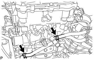
Install the No. 1 water by-pass hose to the cylinder head sub-assembly and slide the clip to secure it.
Install the No. 2 water by-pass hose to the No. 1 water by-pass pipe and slide the clip to secure it.
22271
14.INSTALL THROTTLE BODY GASKET
22030
15.INSTALL THROTTLE BODY WITH MOTOR ASSEMBLY
88431
16.INSTALL NO. 1 COMPRESSOR MOUNTING BRACKET
Install the No. 1 compressor mounting bracket with the 4 bolts.
- Torque:
- 21 N*m (214 kgf*cm, 15 ft.*lbf)
43457
17.INSTALL DRIVE SHAFT BEARING BRACKET
Install the drive shaft bearing bracket with the 3 bolts.
- Torque:
- 63.7 N*m (650 kgf*cm, 47 ft.*lbf)
- NOTICE:
-
Make sure that the bolts and bolt holes are free of oil. Clean them if necessary.
88310
18.INSTALL COMPRESSOR ASSEMBLY WITH PULLEY
for Type A:
Using an E8 "TORX" socket wrench, temporarily install the compressor assembly with pulley with the 2 stud bolts.
- Torque:
- 10 N*m (102 kgf*cm, 7 ft.*lbf)
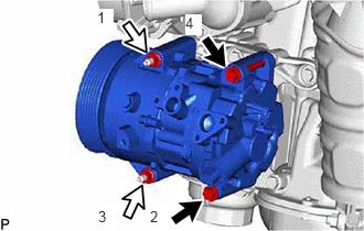

|
Bolt |

|
Nut |
Install the compressor assembly with pulley with the 2 bolts and 2 nuts.
- Torque:
- 24.5 N*m (250 kgf*cm, 18 ft.*lbf)
- HINT:
-
Tighten the bolts and nuts in the order shown in the illustration to install the compressor assembly with pulley.
for Type B:
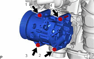
Install the compressor assembly with pulley with the 4 bolts.
- Torque:
- 24.5 N*m (250 kgf*cm, 18 ft.*lbf)
- HINT:
-
Tighten the bolts in the order shown in the illustration to install the compressor assembly with pulley.
19.INSTALL WIRE HARNESS CLAMP BRACKET
Install the wire harness clamp bracket with the bolt.
- Torque:
- 10 N*m (102 kgf*cm, 7 ft.*lbf)
Install the wire harness clamp bracket with the bolt.
- Torque:
- 10 N*m (102 kgf*cm, 7 ft.*lbf)
Install the wire harness clamp bracket with the nut.
- Torque:
- 10 N*m (102 kgf*cm, 7 ft.*lbf)
27020
20.INSTALL GENERATOR ASSEMBLY
16361A
21.INSTALL V-RIBBED BELT
25051
22.INSTALL EXHAUST MANIFOLD CONVERTER SUB-ASSEMBLY
17167
23.INSTALL NO. 1 EXHAUST MANIFOLD HEAT INSULATOR
17139
24.INSTALL NO. 2 MANIFOLD STAY
17118
25.INSTALL MANIFOLD STAY
11452
26.INSTALL ENGINE OIL LEVEL DIPSTICK GUIDE
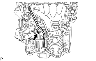
Apply a light coat of engine oil to a new O-ring.
Install the O-ring to the engine oil level dipstick guide.
Install the engine oil level dipstick guide with the bolt.
- Torque:
- 10 N*m (102 kgf*cm, 7 ft.*lbf)
Install the engine oil level dipstick.