6AR-FSE EMISSION CONTROL EGR VALVE INSTALLATION
PROCEDURE

 25620
1.INSTALL EGR VALVE ASSEMBLY
- HINT:
-
Perform "Inspection After Repair" after replacing the EGR valve assembly.
-
Click hereEngine / Hybrid System>6AR-FSE (ENGINE CONTROL)>SFI SYSTEM>INITIALIZATION
Install a new EGR valve gasket to the EGR valve assembly.
Install the EGR valve assembly to the EGR cooler assembly with the 2 nuts.
- Torque:
- 25 N*m (255 kgf*cm, 18 ft.*lbf)
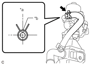
| *a | Up
(When the EGR valve assembly is installed on the engine assembly) |
| *b | Paint Mark |
Connect the No. 1 water by-pass hose to the EGR valve assembly and slide the clip to secure it.
- HINT:
-
Make sure the direction of the clip is as shown in the illustration.
2.INSTALL EGR VALVE WITH COOLER ASSEMBLY
Temporarily install the EGR valve with cooler assembly to the cylinder head sub-assembly with the 2 nuts.
Install a new No. 2 EGR pipe gasket to the EGR valve assembly.
Install a new EGR cooler gasket to the EGR pipe connector.
Install a new EGR cooler gasket to the EGR pipe connector.
Install a new EGR inlet gasket to the intake manifold.
Temporarily connect the No. 2 EGR pipe to the EGR valve assembly with the 2 bolts.
Temporarily connect the EGR pipe connector to the EGR cooler assembly with the 2 bolts.
Temporarily install the No. 2 EGR pipe to the intake manifold with the 2 bolts.
Temporarily install the EGR pipe connector to the exhaust manifold converter sub-assembly (TWC: Front Catalyst) and cylinder block sub-assembly with the 2 bolts and nut.
Tighten the 8 bolts and 3 nuts in the order shown in the illustration.
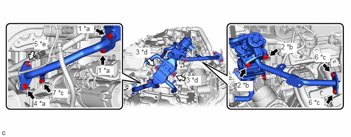
| *a | Bolt (A) | *b | Bolt (B) |
| *c | Bolt (C) | *d | Nut (A) |
| *e | Nut (B) | - | - |

|
Bolt | 
|
Nut |
- Torque:
- Bolt (A) and Nut (B) : 36 N*m (367 kgf*cm, 27 ft.*lbf)
- Bolt (B) : 25 N*m (255 kgf*cm, 18 ft.*lbf)
- Bolt (C) : 10 N*m (102 kgf*cm, 7 ft.*lbf)
- Nut (A) : 21 N*m (214 kgf*cm, 15 ft.*lbf)
Engage the wire harness clamp to the No. 2 EGR pipe.
Temporarily install the 2 EGR valve brackets with the 4 bolts.
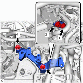
Tighten the 4 bolts in the order shown in the illustration.
- Torque:
- 21 N*m (214 kgf*cm, 15 ft.*lbf)
Install the fuel hose bracket to the EGR valve bracket with the engine cover joint.
- Torque:
- 13 N*m (133 kgf*cm, 10 ft.*lbf)
Connect the No. 4 water by-pass hose to the EGR cooler assembly and slide the clip to secure it.
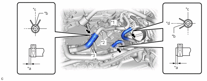
| *1 | No. 2 Water By-pass Hose | *2 | No. 3 Water By-pass Hose |
| *3 | No. 4 Water By-pass Hose | - | - |
| *a | 1 to 6 mm (0.0394 to 0.236 in.) | *b | Paint Mark |
| *c | Up | *d | Left |
- HINT:
-
Make sure the direction of the clip is as shown in the illustration.
Connect the No. 3 water by-pass hose to the EGR cooler assembly and slide the clip to secure it.
- HINT:
-
Make sure the direction of the clip is as shown in the illustration.
Connect the No. 2 water by-pass hose to the EGR valve assembly and slide the clip to secure it.
- HINT:
-
Make sure the direction of the clip is as shown in the illustration.
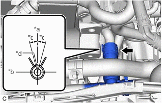
| *a | Up |
| *b | Front |
| *c | 15° |
| *d | Paint Mark |
Connect the water hose sub-assembly to the EGR cooler assembly and slide the clip to secure it.
- HINT:
-
Engage the clip within the area shown in the illustration.
Engage the water hose to the hose clamp.
Connect the EGR valve assembly connector.
82121
3.CONNECT ENGINE WIRE
Connect the engine coolant temperature sensor connector.
Install the bolt.
- Torque:
- 10 N*m (102 kgf*cm, 7 ft.*lbf)
Using an E6 "TORX" socket wrench, connect the engine wire with the stud bolt.
- Torque:
- 5.0 N*m (51 kgf*cm, 44 in.*lbf)
Install the 2 bolts and nut.
- Torque:
- 10 N*m (102 kgf*cm, 7 ft.*lbf)
4.INSTALL FUEL PUMP PROTECTOR
5.INSTALL BATTERY
17705
6.INSTALL AIR CLEANER CAP WITH AIR CLEANER HOSE
7.ADD ENGINE COOLANT
8.INSPECT FOR COOLANT LEAK
9.INSPECT FOR EXHAUST GAS LEAK
12601B
10.INSTALL NO. 1 ENGINE COVER SUB-ASSEMBLY
11.PERFORM INITIALIZATION
Perform "Inspection After Repair" after replacing the EGR valve assembly.
Click hereEngine / Hybrid System>6AR-FSE (ENGINE CONTROL)>SFI SYSTEM>INITIALIZATION