N04C-VQ FUEL FUEL INJECTOR INSTALLATION
PROCEDURE

 11177
1.INSTALL INJECTION NOZZLE SEAT GASKET
Install 4 new injection nozzle seat gaskets to the cylinder head sub-assembly.
23670
2.INSTALL INJECTOR ASSEMBLY
- NOTICE:
-
 3.031,1.281 2.823,0.76 true 2.969,1.302 3.146,1.479 0.177,0.177 10 false *a
-
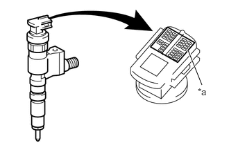
Register the injector compensation code of a new fuel injector assembly in the ECM when replacing the fuel injector assembly. Register the injector compensation code in advance so that it can be installed in the correct position.
| *a | Injector Compensation Code |
Apply a small amount of clean engine oil to 4 new O-rings.
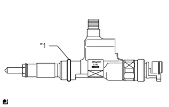
Install the O-ring to each injector assembly as shown in the illustration.
| *1 | O-Ring |
Install a new gasket to each injector assembly.
Referring to each cylinder number identification tag attached to the fuel injector assemblies, insert the fuel injector assembly, nozzle holder clamp, and nozzle holder clamp bolt for each cylinder.
- NOTICE:
- ·
Check that the tip of the fuel injector assembly has no foreign matter attached.
·When reusing the fuel injector assemblies, reinstall them to the same cylinder they were removed from. Otherwise, it could cause the engine to malfunction.
·Carefully insert the fuel injector assembly so that the O-ring is not caught between the cylinder head sub-assembly and the injector assembly.
Temporarily install the 4 nozzle holder clamps with the 4 nozzle holder clamp bolts.
- NOTICE:
-
Be sure to install the holder clamps and nozzle holder clamp bolts in their original positions.
Install 4 new holder seals.
- NOTICE:
-
Securely insert the tip of each holder seal into each fuel injector.
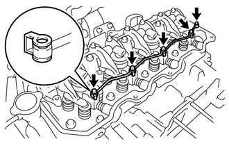
Temporarily install the nozzle leakage pipe assembly and 5 new gaskets with the 5 hollow screws.
- NOTICE:
-
Make sure that the hollow screws and nozzle leakage pipe assembly are not deformed or damaged.
Temporarily install the union nuts of the injection pipe sub-assemblies No. 1, No. 2, No. 3 and No. 4 by hand.
Tighten the 4 nozzle holder clamp bolts.
- Torque:
25 N*m (255 kgf*cm, 18 ft.*lbf)
- NOTICE:
-
After tightening the nozzle holder clamp bolts, check that the fuel injector and the nozzle holder clamp do not interfere with the valve spring.
Tighten the 5 hollow screws.
- Torque:
13 N*m (133 kgf*cm, 10 ft.*lbf)
- NOTICE:
-
If the nozzle leakage pipe assembly has been tightened to more than the specified torque, replace it with a new one.
Using a union nut wrench (17 mm), tighten the 8 union nuts.
- Torque:
- Specified tightening torque:
35 N*m (357 kgf*cm, 26 ft.*lbf)
- HINT:
- ·
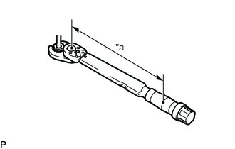
Calculate the torque wrench reading when changing the fulcrum length of the torque wrench.
· 1.688,0.604 2,0.802 0.313,0.198 10 false *a
When using a union nut wrench (fulcrum length of 30 mm (1.18 in.)) + torque wrench (fulcrum length of 180 mm (7.09 in.)): 30 N*m (306 kgf*cm, 22 ft.*lbf)
Text in Illustration *a Torque Wrench Fulcrum Length
23741B
3.INSTALL INJECTION PIPE CLAMP
11213
4.INSTALL CYLINDER HEAD COVER GASKET
11228
5.INSTALL CYLINDER HEAD COVER CUSHION
11202D
6.INSTALL NO. 2 CYLINDER HEAD COVER SUB-ASSEMBLY
11202F
7.INSTALL CYLINDER HEAD COVER CUSHION RUBBER
11201
8.INSTALL CYLINDER HEAD COVER SUB-ASSEMBLY
12180E
9.INSTALL OIL FILLER CAP SUB-ASSEMBLY
25608
10.INSTALL EGR COOLER SUB-ASSEMBLY
11.ADD ENGINE COOLANT
12.CONNECT CABLE TO NEGATIVE BATTERY TERMINAL
13.REGISTER INJECTOR COMPENSATION CODE
14.INSPECT FOR INJECTOR COMPENSATION CODE
15.BLEED AIR FROM FUEL SYSTEM
16.INSPECT FOR FUEL LEAK
17.INSPECT FOR COOLANT LEAK
18.INSPECT FOR OIL LEAK