N04C-VL FUEL FUEL SUPPLY PUMP REMOVAL
PROCEDURE

 58410
1.REMOVE ENGINE SERVICE HOLE COVER
58734B
2.REMOVE REAR ENGINE SERVICE COVER WEATHERSTRIP
58521D
3.REMOVE ENGINE SERVICE HOLE COVER MAT
58420
4.REMOVE NO. 2 ENGINE SERVICE HOLE COVER ASSEMBLY
33504F
5.REMOVE SHIFT KNOB
58534A
6.REMOVE TRANSMISSION COVER MAT
58286
7.REMOVE NO. 1 SHIFT AND SELECT LEVER BOOT
33820B
8.DISCONNECT TRANSMISSION CONTROL CABLE ASSEMBLY
33503F
9.REMOVE FLOOR SHIFT SHIFT LEVER SUB-ASSEMBLY
58701A
10.REMOVE FRONT ENGINE SERVICE COVER PANEL SUB-ASSEMBLY
51441D
11.REMOVE NO. 1 ENGINE UNDER COVER
53712C
12.REMOVE FRONT FENDER APRON LH
13.DRAIN ENGINE COOLANT
14.SET NO. 1 CYLINDER TO TDC / COMPRESSION
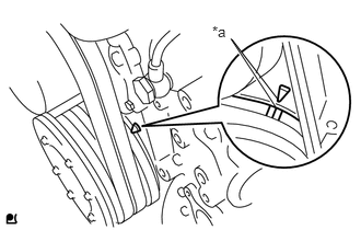
Turn the crankshaft pulley clockwise, and align the matchmarks as shown in the illustration.
If not, turn the crankshaft 1 revolution (360°) and align the matchmarks as above.
| *a | Matchmark |
44360
15.SEPARATE VANE PUMP OIL RESERVOIR ASSEMBLY
17342P
16.REMOVE NO. 2 AIR HOSE
11409
17.REMOVE OIL LEVEL GAUGE GUIDE SUB-ASSEMBLY
18.REMOVE INTAKE PIPE WITH DIESEL THROTTLE BODY
17113
19.REMOVE INTAKE PIPE
22100A
20.DISCONNECT INJECTION PUMP TO FUEL FILTER FUEL HOSE OR PIPE
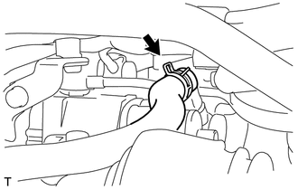
Move the clamp and disconnect the injection pump to fuel filter fuel hose.
21.DISCONNECT NO. 1 FUEL HOSE RETURN TUBE
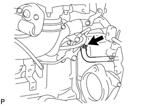
Move the clamp and disconnect the No. 1 fuel hose return tube.
23814D
22.REMOVE FUEL DELIVERY PIPE SUB-ASSEMBLY
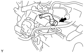
Remove the union bolt, the 2 gaskets and the fuel delivery pipe sub-assembly.
23.REMOVE NO. 2 HARNESS BRACKET
24.REMOVE NO. 1 HARNESS BRACKET
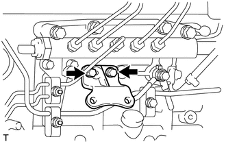
Remove the 2 bolts and the No. 1 harness bracket.
23811
25.REMOVE FUEL FILTER TO INJECTION PUMP FUEL PIPE
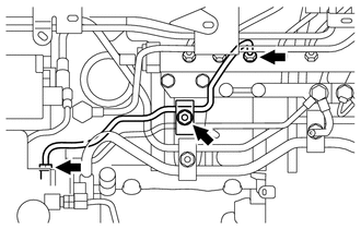
Remove the nut and the fuel pipe clamp.
Using a union nut wrench (17 mm), loosen the 2 union nuts.
Remove the fuel filter to injection pump fuel pipe.
- NOTICE:
-
Be sure to prevent foreign matter or water from entering the lines.
23803H
26.REMOVE FUEL RETURN PIPE SUB-ASSEMBLY
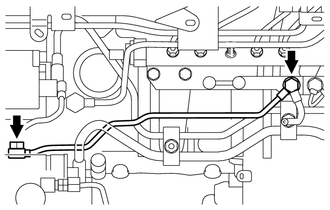
Remove the 2 union bolts and 3 gaskets.
Remove the fuel return pipe sub-assembly and No.4 fuel pipe sub-assembly.
27.REMOVE CRANKSHAFT POSITION SENSOR
22100
28.REMOVE INJECTION OR SUPPLY PUMP ASSEMBLY
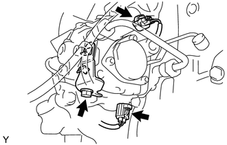
Disconnect the 2 connectors.
Remove the bolt and the holder clip.
- NOTICE:
-
Be sure to prevent foreign matter or water from entering the lines.
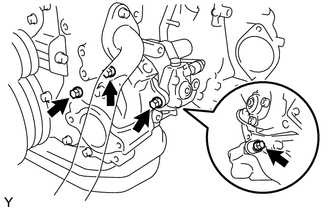
Remove the 4 bolts and the injection or supply pump assembly.
Remove the O-ring from the timer cover.
13613
29.REMOVE INJECTION PUMP DRIVE GEAR
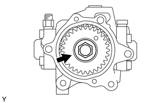
Clamp the injection or supply pump assembly in a soft jaw vise.
Remove the nut, the injection pump drive gear and the crankshaft angle sensor plate.
- NOTICE:
-
Be sure to prevent foreign matter or water from entering the lines.
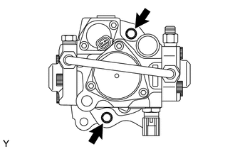
Remove the 2 bolts and the timer cover.
Remove the O-ring from the timer cover.