BRAKE (REAR) REAR BRAKE REASSEMBLY
CAUTION / NOTICE / HINT
- HINT:
- ·
Assemble the parts in the correct direction, as shown.
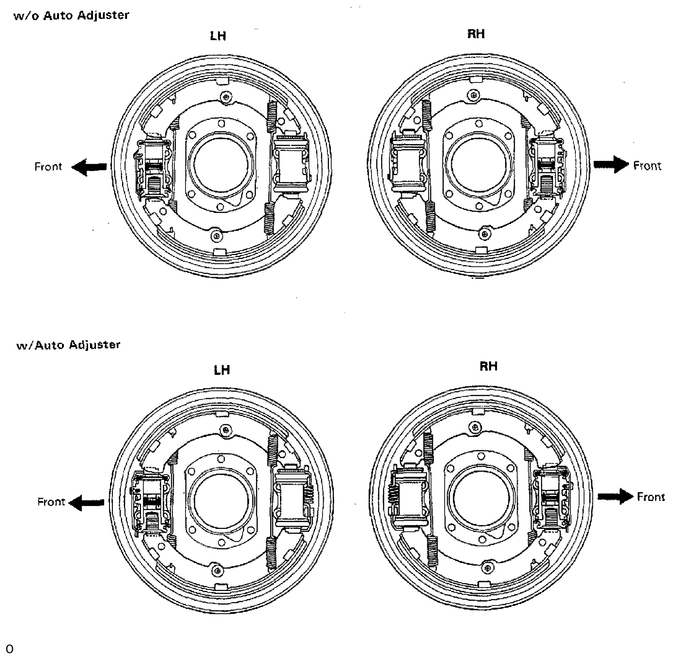
·Replace the inner and outer races with new ones as a set only if the outer races of the bearings are removed.
Applicable Parts Outer Race Removal and Installation Procedure Reusable/Non-reusable
(Replace the inner and outer races as a set.)Rear axle hub inner bearing Procedure performed Non-reusable Procedure not performed Reusable Rear axle hub outer bearing Procedure performed Non-reusable Procedure not performed Reusable
PROCEDURE

 1. ASSEMBLE WHEEL CYLINDER
w/o Auto Adjuster:
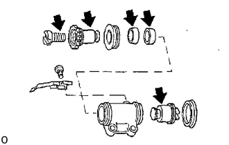
Apply lithium soap base glycol grease to parts, as shown.
Assemble the wheel cylinder.
- HINT:
-
Install in proper direction only.
- ·
2 cups
·Piston
·2 boots
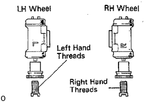
Install the adjusting bolt and nut to the wheel cylinder.
There are 2 kinds of adjusting nuts and bolts. Make sure each location has its correct adjusting nuts and bolts.
RH wheel (R mark) - Right- hand threads
LH wheel (L mark) - Left-hand threads
Install the adjuster lock spring.
w / Auto Adjuster:
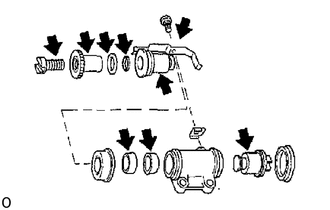
Apply lithium soap base glycol grease to parts, as shown.
Assemble the wheel cylinder.
- HINT:
-
Install in proper direction only.
- ·
2 cups
·Piston
·2 boots
·Wheel cylinder piston subassembly and automaticadjuster lever with spring
·Adjust lever support spring
·Screw
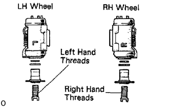
Install the seat and dust seal to the wheel cylinder piston subassembly.
Install the adjusting nut and bolt to the wheel cylinder piston subassembly.
There are 2 kinds of adjusting nuts and bolts. Make sure each location has its correct adjusting nuts and bolts.
RH wheel (R mark) - Right- hand threads
LH wheel (L mark) - Left-hand threads
2.INSTALL BLEEDER PLUG
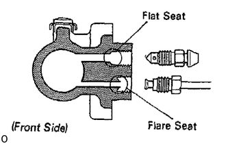
Temporarily install the bleeder plugs, as shown.
- HINT:
- ·
Front side wheel cylinder union seats are flat and flare shaped, as shown.
·Both union seats of rear side wheel cylinder are flared.
3.INSTALL WHEEL CYLINDERS
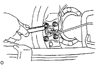
Install the front side wheel cylinders with the adjuster facing downward.
Install the rear side wheel cylinder with the adjuster facing upward.
- HINT:
-
The cut-out part of the piston head should be facing toward the center of the axle.
Torque the bolts.
- Torque:
61 N*m (620 kgf*cm, 45 ft.*lbf)
4.INSTALL BRAKE LINE TO WHEEL CYLINDER
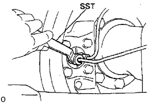
After tightening by finger, tighten the nut with SST.
- SST
- 09751-36011
- Torque:
15 N*m (155 kgf*cm, 11 ft.*lbf)
5.INSTALL BRAKE TUBE CLAMP
6.INSTALL BRAKE SHOES AND RETURN SPRINGS
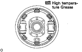
Apply high temperature grease to the brake shoe contact surfaces, as shown.
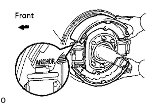
Hook the return spring to the brake shoe front inner side.
Install the brake shoes.
- HINT:
-
When the shoe with "ANCHOR" written on it is properly installed, the projection of the shoe fits into the cut- out of the piston head.
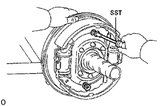
Using SST, install the shoe hold-down springs, cups and pins.
SST 09718-00010
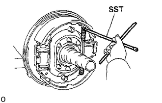
Using SST, install the other side return spring.
SST 09703-30010
7.CLEAN LINING AND INNER DRUM WITH SANDPAPER
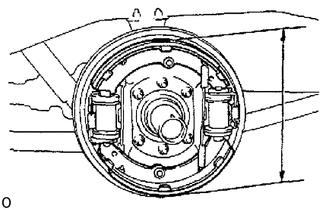
8. CHECK CLEARANCE BETWEEN BRAKE SHOES AND DRUM (w/ Auto Adjuster)
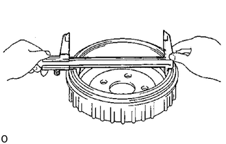
Measure the brake drum inside diameter and diameter of the brake shoes. Check that the difference between the diameter is the correct shoe clearance.
- Reference clearance:
less than 0.5 mm (0.02 in.)
9.INSTALL DRUM WITH AXLE HUB
10. FILL BRAKE RESERVOIR WITH BRAKE FLUID AND BLEED BRAKE SYSTEM
w/ Brake pedal Load Sensing Switch
Click hereBrake>BRAKE SYSTEM (OTHER)>BRAKE FLUID (w/ Brake pedal Load Sensing Switch)>BLEEDING
w/o Brake pedal Load Sensing Switch
Click hereBrake>BRAKE SYSTEM (OTHER)>BRAKE FLUID (w/o Brake pedal Load Sensing Switch)>BLEEDING
11. CHECK FLUID LEAKAGE
12.ADJUST BRAKE SHOE CLEARANCE (w/o Auto Adjuster)
Click hereBrake>BRAKE (REAR)>REAR BRAKE>ADJUSTMENT
13.ADJUST PRELOAD
14.INSTALL LOCK NUT PLATE
15.INSTALL REAR AXLE SHAFT
16.INSTALL WHEELS