A861E AUTOMATIC TRANSMISSION / TRANSAXLE AUTOMATIC TRANSMISSION SYSTEM P0748 Pressure Control Solenoid "A" Electrical P0778 Pressure Control Solenoid "B" Electrical
DESCRIPTION
The transmission control ECU assembly controls gear shifting between 1st and 6th gears based on the combination of the SL1, SL2, SL3, S1, S2, and S3 solenoids. If there is an open or short in any of the solenoid valves, the transmission control ECU assembly turns the other solenoid valves on or off as part of fail-safe operation. Also, if all of the solenoid valves malfunction, only the mechanical hydraulic circuits will be available, and shifting will be manual only. (In the case of an open or short, the transmission control ECU assembly cuts the electrical power supply to the malfunctioning solenoid valve.)
| DTC No. | Detection Item | DTC Detection Condition | Trouble Area | Warning Indicate | Memory |
|---|---|---|---|---|---|
| P0748 | Pressure Control Solenoid "A" Electrical | 1. Diagnosis Condition 2. Malfunction Status 3. Malfunction Time 4. Other
DTC Detection Condition 1:
1.
- 2.
Shift solenoid valve SL1 resistance 100 kΩ or more 3.
0.065 seconds or more 4.
1 trip detection logic DTC Detection Condition 2:
1.
- 2.
Shift solenoid valve SL1 current 4 A or more 3.
0.1 seconds or more 4.
1 trip detection logic |
·
Wire harness or connector (Shift solenoid valve SL1 signal circuit) ·
No. 1 transmission wire ·
Transmission valve body assembly (Shift solenoid valve SL1) ·
Transmission control ECU assembly |
O/D OFF Indicator Light: Blinking | DTC stored |
| P0778 | Pressure Control Solenoid "B" Electrical | 1. Diagnosis Condition 2. Malfunction Status 3. Malfunction Time 4. Other
DTC Detection Condition 1:
1.
- 2.
Shift solenoid valve SL2 resistance 100 kΩ or more 3.
0.065 seconds or more 4.
1 trip detection logic DTC Detection Condition 2:
1.
- 2.
Shift solenoid valve SL2 current 4 A or more 3.
0.1 seconds or more 4.
1 trip detection logic |
·
Wire harness or connector (Shift solenoid valve SL2 signal circuit) ·
No. 2 transmission wire ·
Transmission valve body assembly (Shift solenoid valve SL2) ·
Transmission control ECU assembly |
O/D OFF Indicator Light: Blinking | DTC stored |
CONFIRMATION DRIVING PATTERN
- HINT:
-
After the repair, clear the DTCs and perform the following procedure to check that DTCs are not output.
Perform the D Position Shift Test inspection in Road Test.
Click hereDrivetrain>A861E (AUTOMATIC TRANSMISSION / TRANSAXLE)>AUTOMATIC TRANSMISSION SYSTEM>ROAD TEST
Check for DTCs again.
WIRING DIAGRAM
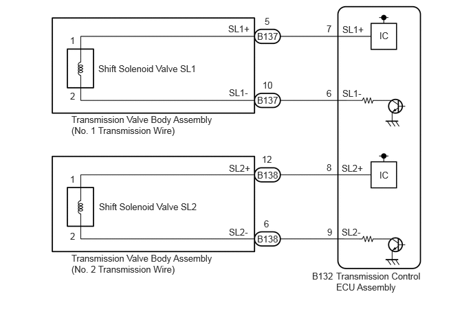
CAUTION / NOTICE / HINT
- NOTICE:
- ·
When inspecting each shift solenoid valve, do not remove it from the transmission valve body assembly.
·Perform initialization when parts related to the automatic transmission are replaced.
Click hereDrivetrain>A861E (AUTOMATIC TRANSMISSION / TRANSAXLE)>AUTOMATIC TRANSMISSION SYSTEM>INITIALIZATION
- HINT:
- ·
Refer to Parts Location for the location of each shift solenoid valve and each oil pressure switch.
Click hereDrivetrain>A861E (AUTOMATIC TRANSMISSION / TRANSAXLE)>AUTOMATIC TRANSMISSION SYSTEM>PARTS LOCATION
·Use a new transmission wire if the pin and socket terminals are removed on each oil pressure switch.
PROCEDURE
Disconnect the No. 1 transmission wire connector.
Disconnect the No. 2 transmission wire connector.
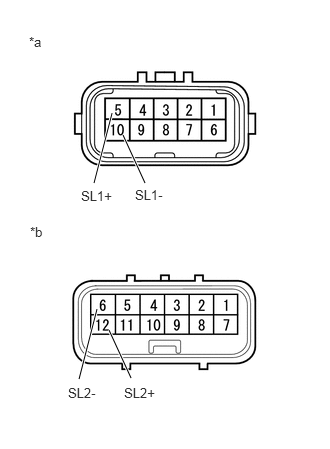
| *a | Component without harness connected
(No. 1 Transmission Wire) |
| *b | Component without harness connected
(No. 2 Transmission Wire) |
Measure the resistance according to the value(s) in the table below.
- Standard Resistance:
Tester Connection Condition Specified Condition 5 (SL1+) - 10 (SL1-) 20°C (68°F) 5.0 to 6.0 Ω 12 (SL2+) - 6 (SL2-) 20°C (68°F) 5.0 to 6.0 Ω 5 (SL1+) or 10 (SL1-) - Body ground Always 10 kΩ or higher 12 (SL2+) or 6 (SL2-) - Body ground Always 10 kΩ or higher
- Result:
Result Proceed to OK A NG (Shift solenoid valve SL1) B NG (Shift solenoid valve SL2) C
A
B
C
Disconnect the transmission control ECU assembly connector.
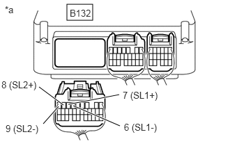
| *a | Rear view of wire harness connector
(to Transmission Control ECU Assembly) |
Measure the resistance according to the value(s) in the table below.
- Standard Resistance:
Tester Connection Condition Specified Condition B132-7 (SL1+) - B132-6 (SL1-) 20°C (68°F) 5.0 to 6.0 Ω B132-8 (SL2+) - B132-9 (SL2-) 20°C (68°F) 5.0 to 6.0 Ω B132-7 (SL1+) or B132-6 (SL1-) - Body ground Always 10 kΩ or higher B132-8 (SL2+) or B132-9 (SL2-) - Body ground Always 10 kΩ or higher
- Result:
Proceed to OK NG
OK
NG
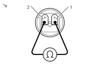
| *a | Component without harness connected
(Shift Solenoid Valve SL1) |
Disconnect the shift solenoid valve SL1 connector.
Click hereDrivetrain>A861E (AUTOMATIC TRANSMISSION / TRANSAXLE)>AUTOMATIC TRANSMISSION SYSTEM>PARTS LOCATION
- NOTICE:
-
When inspecting the shift solenoid valve SL1, do not remove it from the transmission valve body assembly.
Measure the resistance according to the value(s) in the table below.
- Standard Resistance:
Tester Connection Condition Specified Condition 1 - 2 20°C (68°F) 5.0 to 6.0 Ω
- Result:
Proceed to OK NG
OK
NG
| *a | Component without harness connected
(Shift Solenoid Valve SL2) |
Disconnect the shift solenoid valve SL2 connector.
Click hereDrivetrain>A861E (AUTOMATIC TRANSMISSION / TRANSAXLE)>AUTOMATIC TRANSMISSION SYSTEM>PARTS LOCATION
- NOTICE:
-
When inspecting the shift solenoid valve SL2, do not remove it from the transmission valve body assembly.
Measure the resistance according to the value(s) in the table below.
- Standard Resistance:
Tester Connection Condition Specified Condition 1 - 2 20°C (68°F) 5.0 to 6.0 Ω
- Result:
Proceed to OK NG
OK
NG