N04C-WA ENGINE CONTROL ECD SYSTEM P1270 Fuel Pressure Regulator Malfunction
DESCRIPTION
| DTC No. | Detection Item | DTC Detection Condition | Trouble Area | MIL | Memory |
|---|---|---|---|---|---|
| P1270 | Fuel Pressure Regulator Malfunction | Diagnosis Condition:
·
When the following conditions continue for at least 5 seconds -
Supply pump assembly is not in stop-operation mode. -
Fuel injection quantity is less than 0 mm3/st. -
Actual fuel injection quantity exceeds required injection value, and which is lower than specification. -
ECM works function normally, and inputs NE pulse signal from the crankshaft position sensor. -
Difference of common rail pressure between begin of injection and end of injection is lower than a certain value of pressure. -
Ignition switch ON -
Battery voltage is in the range of 10 V to 16 V Malfunction Status: Actual fuel discharge quantity exceeds threshold of calculated discharge quantity by common rail pressure. Malfunction Duration: - |
·
Pressure discharge valve ·
Harness or connector ·
Fuel filter element sub-assembly |
- | DTC stored |
MONITOR DESCRIPTION
Common rail pressure is controlled by a discharge rate of the supply pump assembly and pressure discharge valve.
Discharge rate of the supply pump assembly is adjusted by the suction control valve.
CONFIRMATION DRIVING PATTERN
| DTC No. | DTC Detection Drive Pattern |
|---|---|
| P1270 | Race the engine from idling to 2500 rpm for 35 seconds after idling for 60 seconds. |
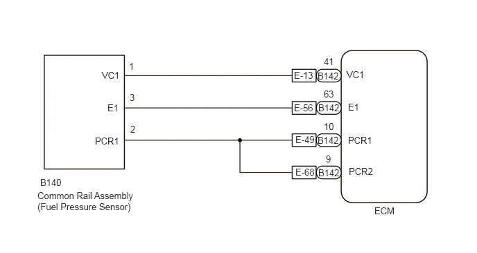
WIRING DIAGRAM
CAUTION / NOTICE / HINT
- NOTICE:
- ·
After replacing the ECM, the new ECM needs registration (Click hereEngine / Hybrid System>N04C-WA (ENGINE CONTROL)>ECD SYSTEM>REGISTRATION) and initialization (Click hereEngine / Hybrid System>N04C-WA (ENGINE CONTROL)>ECD SYSTEM>INITIALIZATION).
·After replacing the suction control valve or supply pump assembly, the ECM needs initialization (Click hereEngine / Hybrid System>N04C-WA (ENGINE CONTROL)>ECD SYSTEM>INITIALIZATION).
- HINT:
-
Read freeze frame data using the GTS. Freeze frame data records the engine condition when malfunctions are detected. When troubleshooting, freeze frame data can help determine if the vehicle was moving or stationary, if the engine was warmed up or not, and other data from the time the malfunction occurred.
PROCEDURE
Connect the GTS to the DLC3.
Turn the ignition switch to ON.
Turn the GTS on.
Enter the following menus: Powertrain / Engine / Trouble Codes.
Read the DTCs.
- Result:
Result Proceed to DTC P1270 is output A P0088, P016E and/or P1270 and other DTCs are output B
A
B
Check that the fuel meets to require with ambient air temperature.
- Result:
Proceed to OK NG
OK
NG
Check if fuel is leaking or seeping out of the supply pump assembly.
- Result:
Proceed to OK NG
OK
NG
Check the fuel filter element sub-assembly.
Check the replacement period expired.
Check the damage or clogging of the fuel filter element sub-assembly.
Is it a genuine part?
Check the fuel filter connections for air breathing and fuel leakage.
- HINT:
-
If the air bleeding plug is loosened, it is caused by breathing the air into the fuel system.
- Standard:
Condition Specified Condition Ignition switch off Below the upper level of the fuel filter element Engine running Fuel level does not continue dropping while engine is running at high speed
- Result:
Proceed to OK NG
OK
NG
Check if the fuel pipe and hose between the fuel tank and pre fuel filter are clogged, punctured, or bent.
Make sure the fuel pipe joint bolts are not loose.
Check the fuel filter connections for air breathing and fuel leakage.
- HINT:
-
If the air bleeding plug is loosened, it is caused by breathing the air into the fuel system.
- Result:
Proceed to OK NG
OK
NG
Make sure the fuel tank feed pipe is not clogging.
- Result:
Proceed to OK NG
OK
NG
Check if the breather hose is clogged, punctured, or bent.
Make sure the check valve is functioning normally.
- Result:
Proceed to OK NG
OK
NG
Drain fuel out of the fuel tank and check if there are foreign objects inside the tank.
- Result:
Proceed to OK NG
OK
NG
Make sure the fuel high-pressure pipe is not leaking fuel.
Check the common rail for fuel leakage.
- Result:
Proceed to OK NG
OK
NG
Check the fuel filter element set.
Check the replacement period expired.
Check the damage or clogging of the fuel filter element.
Is it a genuine part?
Check for bleeding the air from the fuel filter at adequate levels.
Check the fuel filter connections for breathing the air and fuel leakage.
- HINT:
-
If the air bleeding plug is loosened, it is caused by breathing the air into the fuel system.
- Result:
Proceed to OK NG
OK
NG
Check the connector connection for the fuel pressure sensor connector.
- Standard:
The connector is connected securely and there are no contact pressure problems.
- Result:
Proceed to OK NG
OK
NG
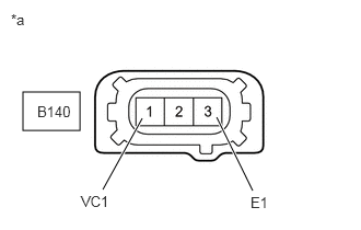
| *a | Front view of wire harness connector
(to Fuel Pressure Sensor ) |
Disconnect the fuel pressure sensor connector.
Turn the ignition switch to ON.
Measure the voltage according to the value(s) in the table below.
- Standard Voltage:
Tester Connection Switch Condition Specified Condition B140-1 (VC1) - B140-3 (E1) Ignition switch ON 4.5 to 5.5 V
- Result:
Proceed to OK NG
OK
NG
Connect the GTS to the DLC3.
Turn the ignition switch to ON.
Turn the GTS on.
Enter the following menus: Powertrain / Engine / Data List / Common Rail Pressure, NE Active Status, G Active Status
Start the engine, and let it idle.
Check whether "Common Rail Pressure" changes when the harness between the ECM and fuel pressure senor is jiggled.
Jiggle the harness between the ECM and crankshaft position sensor, and the harness between the ECM and camshaft position sensor. Check whether "NE Active Status" and "G Active Status" change as the harnesses are jiggled.
- Standard:
No change when harness is jiggled.
- Result:
Proceed to OK NG
OK
NG
Check the connector connection for the pressure discharge valve.
- Standard:
The connector is connected securely and there are no contact pressure problems.
- Result:
Proceed to OK NG
OK
NG
Inspect the pressure discharge valve.
Click hereEngine / Hybrid System>N04C-WA (FUEL)>COMMON RAIL>INSPECTION
- Result:
Proceed to OK NG
OK
NG
Check the connector connection for the suction control valve.
- Standard:
The connector is connected securely and there are no contact pressure problems.
- Result:
Proceed to OK NG
OK
NG
Inspect the suction control valve.
Click hereEngine / Hybrid System>N04C-WA (FUEL)>FUEL SUPPLY PUMP>INSPECTION
- Result:
Proceed to OK NG
OK
NG
Check if the fuel return pipe and hose are clogged, punctured, or bent.
- Result:
Proceed to OK NG
OK
NG
Connect the GTS to the DLC3.
Turn the ignition switch to ON and turn the GTS on.
Clear the DTCs.
- HINT:
-
Clear the DTCs with the engine stopped, as DTCs cannot be cleared while the engine is running.
Start the engine and warm it up until the engine coolant temperature reaches 80°C (176°F) or higher.
Turn the ignition switch off for 30 seconds or more.
Perform the confirmation driving pattern.
Turn the GTS on.
Enter the following menus: Powertrain / Engine / Trouble Codes.
Read Current DTCs.
- Result:
Result Proceed to DTC P1270 is output A DTCs are not output B
A
B
Replace the common rail assembly.
Click hereEngine / Hybrid System>N04C-WA (FUEL)>COMMON RAIL>REMOVAL
- Result:
Proceed to NEXT
NEXT
Connect the GTS to the DLC3.
Turn the ignition switch to ON and turn the GTS on.
Clear the DTCs.
- HINT:
-
Clear the DTCs with the engine stopped, as DTCs cannot be cleared while the engine is running.
Start the engine and warm it up until the engine coolant temperature reaches 80°C (176°F) or higher.
Turn the ignition switch off for 30 seconds or more.
Perform the confirmation driving pattern.
Turn the GTS on.
Enter the following menus: Powertrain / Engine / Trouble Codes.
Read Current DTCs.
- Result:
Result Proceed to DTC P1270 is output A DTCs are not output B
A
B
Repair or replace the fuel filter element set.
- Result:
Proceed to NEXT
NEXT
Repair or replace the faulty part.
- Result:
Proceed to NEXT
NEXT
Repair or replace the fuel return pipe and hose.
- Result:
Proceed to NEXT
NEXT
Drain fuel out of the fuel tank and check if there are foreign objects inside the tank.
- Result:
Result Proceed to Malfunction symptom improved during inspection A Malfunction symptom does not improve during inspection
(check other areas for cause of malfunction)B
A
B
Replace the suction control valve.
Click hereEngine / Hybrid System>N04C-WA (FUEL)>SUCTION CONTROL VALVE>REMOVAL
- Result:
Proceed to NEXT
NEXT
Connect securely the suction control valve connector.
- HINT:
-
Repair it as needed.
- Result:
Proceed to NEXT
NEXT
Repair or replace the fuel tank breather.
- Result:
Proceed to NEXT
NEXT
Replace the common rail assembly.
Click hereEngine / Hybrid System>N04C-WA (FUEL)>COMMON RAIL>REMOVAL
- Result:
Proceed to NEXT
NEXT
Repair or replace the fuel pipe.
- Result:
Proceed to NEXT
NEXT
Connect securely the pressure discharge valve connector.
- HINT:
-
Repair it as needed.
- Result:
Proceed to NEXT
NEXT
Repair or replace the fuel pipe.
- Result:
Proceed to NEXT
NEXT
Repair or replace the harness or connector.
- Result:
Proceed to NEXT
NEXT
Repair or replace the fuel filter element sub-assembly.
- Result:
Result Proceed to Malfunction symptom improved during inspection A Malfunction symptom does not improve during inspection
(check other areas for cause of malfunction)B
A
B
Repair or replace the harness or connector.
- Result:
Proceed to NEXT
NEXT
Connect securely the fuel pressure sensor connector.
- HINT:
-
Repair it as needed.
- Result:
Proceed to NEXT
NEXT
Repair or replace the supply pump assembly.
- Result:
Result Proceed to Malfunction symptom improved during inspection A Malfunction symptom does not improve during inspection
(check other areas for cause of malfunction)B
A
B
Replace fuel with required ambient temperature.
- Result:
Proceed to NEXT
NEXT