N04C-WA EMISSION CONTROL UREA SELECTIVE CATALYTIC REDUCTION SYSTEM P204915 Reductant Injection Valve Circuit High Bank 1 Unit 1 Circuit Short to Battery or Open
DESCRIPTION
The urea injector assembly is controlled by the DCU (emission control ECU assembly).
Disconnections and short circuits in the urea injector assembly are detected by the DCU (emission control ECU assembly).
| DTC No. | Detection Item | DTC Detection Condition | Trouble Area | MIL | Warning Indicate | Memory |
|---|---|---|---|---|---|---|
| P204915 | Reductant Injection Valve Circuit High Bank 1 Unit 1 Circuit Short to Battery or Open | Diagnosis Condition:
·
The urea injector assembly is not activated. Malfunction Status: ·
The urea injector assembly voltage is higher than 0.562 V. Malfunction Duration: ·
0.2 seconds or more. |
·
Open or short in urea injector assembly circuit ·
Urea injector assembly ·
DCU (emission control ECU assembly) |
Class A | AdBlue consumption warning light:
Comes on |
DTC stored |
MONITOR DESCRIPTION
- Description of malfunction
-
Urea injector assembly failure is detected.
- Reset condition
-
After having restored to the normal conditions.
CONFIRMATION DRIVING PATTERN
| DTC No. | DTC Detection Drive Pattern |
|---|---|
| P204915 | Perform forced operation of the "Control the Reductant Injector Duty Ratio" Active Test at 50% for 1 second or more. |
WIRING DIAGRAM
Refer to DTC P202E71.
Click hereEngine / Hybrid System>N04C-WA (EMISSION CONTROL)>UREA SELECTIVE CATALYTIC REDUCTION SYSTEM>P202E71
CAUTION / NOTICE / HINT
- HINT:
-
Read freeze frame data using the GTS. Freeze frame data records the engine condition when malfunctions are detected. When troubleshooting, freeze frame data can help determine if the vehicle was moving or stationary, if the engine was warmed up or not, and other data from the time the malfunction occurred.
PROCEDURE
Check the connector connection and contact pressure of the urea injector assembly connector.
- OK:
The connector is connected securely and there are no contact pressure problems.
- Result:
Proceed to OK NG
OK
NG
Inspect the urea injector assembly.
Click hereEngine / Hybrid System>N04C-WA (EMISSION CONTROL)>UREA INJECTOR>INSPECTION
- Result:
Proceed to OK NG
OK
NG
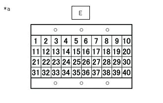
| *a | Signal Check Harness No. 2 Lead Connector |
Connect the signal check harness No. 2 to the DCU (emission control ECU assembly) vehicle side harness. (Do not connect the harness to the DCU (emission control ECU assembly).)
Measure the resistance according to the value(s) in the table below.
- Standard Resistance:
Tester Connection Condition Specified Condition E-6 (UIV+) - Body ground Ignition switch off 10 kΩ or higher E-7 (UIV-) - Body ground Ignition switch off 10 kΩ or higher
- Result:
Proceed to OK NG
OK
NG
| *a | Signal Check Harness No. 2 Lead Connector |
Connect the urea injector assembly connector.
Connect the signal check harness No. 2 to the DCU (emission control ECU assembly) vehicle side harness. (Do not connect the harness to the DCU (emission control ECU assembly).)
Measure the resistance according to the value(s) in the table below.
- Standard Resistance:
Tester Connection Condition Specified Condition E-6 (UIV+) -E-7 (UIV-) Ignition switch off 17 Ω or less
- Result:
Proceed to OK NG
OK
NG
Connect the GTS to the DLC3.
Turn the ignition switch to ON.
Turn the GTS on.
Clear the DTCs.
- NOTICE:
-
Clear the DTCs with the engine stopped, as DTCs cannot be cleared while the engine is running.
Turn the ignition switch off and wait for at least 30 seconds.
- Result:
Proceed to NEXT
NEXT
Drive the vehicle in accordance with the driving pattern described in the Confirmation Driving Pattern.
Connect the GTS to the DLC3.
Turn the ignition switch to ON.
Turn the GTS on.
Enter the following menus: Powertrain / Urea Selective Catalytic Reduction / Trouble Codes.
Read the DTCs.
- Result:
Result Proceed to DTC P204915 is output A DTCs are not output B
A
B
Replace the DCU (emission control ECU assembly).
Click hereEngine / Hybrid System>N04C-WA (EMISSION CONTROL)>UREA PUMP CONTROL ECU>REMOVAL
- HINT:
-
Perform DPR forced regeneration after DCU (emission control ECU assembly) replacement.
-
Click hereEngine / Hybrid System>N04C-WA (EMISSION CONTROL)>EMISSION CONTROL SYSTEM>ON-VEHICLE INSPECTION
- Result:
Proceed to NEXT
NEXT
Repair or replace the harness or connector.
- Result:
Proceed to NEXT
NEXT
Repair or replace the harness or connector.
- Result:
Proceed to NEXT
NEXT
Replace the urea injector assembly.
Click hereEngine / Hybrid System>N04C-WA (EMISSION CONTROL)>UREA INJECTOR>REMOVAL
- Result:
Proceed to NEXT
NEXT
Securely connect the urea injector assembly connector.
- HINT:
-
Repair parts as necessary.
- Result:
Proceed to NEXT
NEXT
Connect the GTS to the DLC3.
Turn the ignition switch to ON.
Turn the GTS on.
Clear the DTCs.
- NOTICE:
-
Clear the DTCs with the engine stopped, as DTCs cannot be cleared while the engine is running.
Turn the ignition switch off and wait for at least 30 seconds.
- Result:
Proceed to NEXT
NEXT
Drive the vehicle in accordance with the driving pattern described in the Confirmation Driving Pattern.
Connect the GTS to the DLC3.
Turn the ignition switch to ON.
Turn the GTS on.
Enter the following menus: Powertrain / Urea Selective Catalytic Reduction / Trouble Codes.
Read the DTCs.
- OK:
DTCs are not output
- Result:
Proceed to NEXT
NEXT