N04C-WA EMISSION CONTROL UREA SELECTIVE CATALYTIC REDUCTION SYSTEM P20F49C Reductant Consumption Too Low Low/Insufficient Flow
DESCRIPTION
The urea solution injection volume is diagnosed as abnormal.
The urea solution injection volume is controlled by the urea solution pressure and the opening of the urea injector assembly.
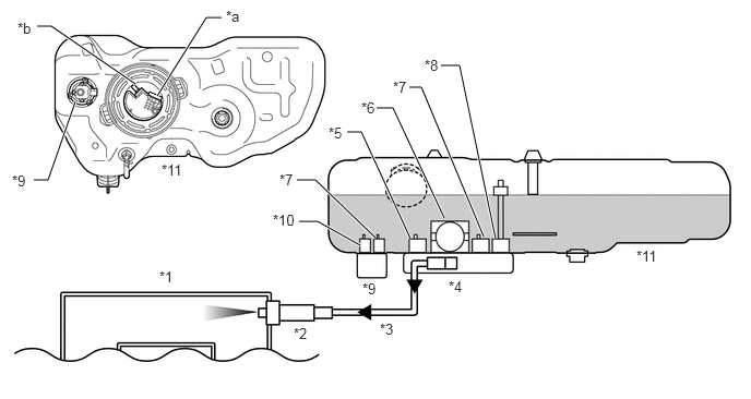
| *1 | Muffler | *2 | Urea Injector Assembly |
| *3 | Urea Tube with Heater Assembly | *4 | Urea Pump |
| *5 | Pressure Sensor | *6 | Pump Motor |
| *7 | Temperature Sensor | *8 | Level Sensor |
| *9 | Urea Sensor Assembly | *10 | Urea Solution Quality Sensor |
| *11 | Urea Tank | - | - |
| *a | Harness Connector | *b | Pressure Line |
| DTC No. | Detection Item | DTC Detection Condition | Trouble Area | MIL | Warning Indicate | Memory |
|---|---|---|---|---|---|---|
| P20F49C | Reductant Consumption Too Low Low/Insufficient Flow | Diagnosis Condition:
·
The total urea solution injection volume is higher than 1 g. ·
Ambient temperature is higher than -7°C (19.4°F). ·
The battery voltage is 8 to 16 V. Malfunction Status: ·
The estimated urea solution injection volume is 60% or less of the requested urea solution injection volume. Malfunction Duration: ·
- |
·
Open or short in urea injector assembly circuit ·
Urea injector assembly ·
Urea tube with heater assembly ·
DCU (emission control ECU assembly) |
Class A | AdBlue consumption warning light:
Comes on |
DTC stored |
MONITOR DESCRIPTION
- Description of malfunction
-
Failure of urea injector assembly during system operation is detected.
- Reset condition
-
After having restored to the normal conditions.
CONFIRMATION DRIVING PATTERN
| DTC No. | DTC Detection Drive Pattern |
|---|---|
| P20F49C | Perform "Pattern 2" of the "Reductant Injection" Utility. |
WIRING DIAGRAM
Refer to DTC P202E71.
Click hereEngine / Hybrid System>N04C-WA (EMISSION CONTROL)>UREA SELECTIVE CATALYTIC REDUCTION SYSTEM>P202E71
CAUTION / NOTICE / HINT
- NOTICE:
- Handling urea solution·
Wear protective equipment as necessary (protective glasses and gloves).
·Do not dilute urea solution.
·If urea solution contacts your eyes or skin, immediately wash the contacted area with a large amount of water and consult a doctor as necessary.
·If urea solution dries, it deposits a white powder. Also, if urea solution contacts metals such as copper and aluminum for a long period of time, it may promote corrosion. Therefore, if urea solution is spilled, dampen a cloth or other item and wipe it up or rinse the area with cool or warm water.
- Handling the urea injector assembly·
The urea injector assembly is a precision instrument. Take necessary precautions for installation and shipping. Do not use the part if it has been struck or dropped.
·If the urea solution remaining inside the urea injector assembly dries out, it may become unable to inject urea solution. Therefore, conduct urea tube with heater assembly installation and removal quickly.
·If the urea solution dries out and deposition occurs, urea may cling to the O-ring of the pipe and cause seal problems. Therefore, clean the urea tube with heater assembly and intake port of the urea injector assembly with water before attaching them.
·Perform this procedure in an environment where urea solution will not freeze.
- HINT:
-
Read freeze frame data using the GTS. Freeze frame data records the engine condition when malfunctions are detected. When troubleshooting, freeze frame data can help determine if the vehicle was moving or stationary, if the engine was warmed up or not, and other data from the time the malfunction occurred.
PROCEDURE
While checking the refill check tube, refill the urea solution until the tank level is half full or more.
Disconnect the urea tube with heater assembly from the urea injector assembly.
Click hereEngine / Hybrid System>N04C-WA (EMISSION CONTROL)>UREA INJECTOR>REMOVAL
- NOTICE:
-
If the urea solution remaining inside the urea injector assembly dries out, it may become unable to inject urea solution. Therefore, seal the urea injector assembly with an item such as a cover or rubber cap so that the inside does not dry out.
Prepare a bucket or other receptacle for collecting urea solution from the urea tube with heater assembly.
Connect the GTS to the DLC3.
Turn the ignition switch to ON.
Turn the GTS on.
Enter the following menus: Powertrain / Urea Selective Catalytic Reduction / Utility / Reductant Discharge.
Perform the Utility and check the Reductant Pump Pressure.
- Result:
Result Proceed to Except below A Reductant Pump Pressure is 4.5 to 5.5 bar B
- HINT:
-
If the Utility fails, troubleshoot the error message and perform the Utility again.
A
B
Remove the urea injector assembly from the front exhaust pipe assembly.
- HINT:
- ·
Do not disconnect the urea injector assembly from the urea tube with heater assembly.
·Use a cover, etc., to prevent foreign matter from entering the exhaust pipe.
Connect the GTS to the DLC3.
Turn the ignition switch to ON.
Turn the GTS on.
Enter the following menus: Powertrain / Urea Selective Catalytic Reduction / Utility / Pressure Rising Diagnosis (Leak Test).
Perform the Utility and check that there are no urea solution leaks in the urea injector assembly and the area from the urea injector assembly to the urea pump.
- OK:
No urea solution leaks in urea injector assembly and area from urea injector assembly to urea pump.
- Result:
Proceed to OK NG
- HINT:
-
If the Utility fails, troubleshoot the error message and perform the Utility again.
OK
NG
While checking the refill check tube, refill the urea solution until the tank level is half full or more.
Remove the urea injector assembly from the front exhaust pipe assembly.
Click hereEngine / Hybrid System>N04C-WA (EMISSION CONTROL)>UREA INJECTOR>REMOVAL
- HINT:
- ·
Do not disconnect the urea injector assembly from the urea tube with heater assembly.
·Use a cover, etc., to prevent foreign matter from entering the exhaust pipe.
Prepare a bucket or other receptacle for collecting urea solution from the urea injector assembly.
Connect the GTS to the DLC3.
Turn the ignition switch to ON.
Turn the GTS on.
Enter the following menus: Powertrain / Urea Selective Catalytic Reduction / Utility / Reductant Injection / Pattern 3.
Perform "Pattern 3" and check the urea solution injection.
- OK:
Urea solution injects from urea injector assembly.
- Result:
Proceed to OK NG
OK
NG
While checking the refill check tube, refill the urea solution until the tank level is half full or more.
Remove the urea injector assembly from the front exhaust pipe assembly.
Click hereEngine / Hybrid System>N04C-WA (EMISSION CONTROL)>UREA INJECTOR>REMOVAL
- HINT:
- ·
Do not disconnect the urea injector assembly from the urea tube with heater assembly.
·Use a cover, etc., to prevent foreign matter from entering the exhaust pipe.
Prepare a bucket or other receptacle for collecting urea solution from the urea injector assembly.
Connect the GTS to the DLC3.
Turn the ignition switch to ON.
Turn the GTS on.
Enter the following menus: Powertrain / Urea Selective Catalytic Reduction / Utility / Reductant Injection / Pattern 3.
Perform "Pattern 3" and check the urea solution injection volume.
- Standard Value:
Reductant Injection Urea Solution Injection Volume Pattern 3 45 to 55 cc
- NOTICE:
-
The measured value is within the standard value at least once during 3 times.
- HINT:
-
Crystallized urea solution dissolves in urea solution, so blockages can be cleared by repeatedly supplying and injecting urea solution.
-
Therefore, even if crystals accumulate on the tip of the injector, the above injection is possible and it is not a malfunction.
- Result:
Proceed to OK NG
OK
NG
Enter the following menus: Powertrain / Urea Selective Catalytic Reduction / Utility / Reductant Injection / Pattern 2.
Perform "Pattern 2" and check the urea solution injection volume.
- Standard Value:
Reductant Injection Urea Solution Injection Volume Pattern 2 16 to 24 cc
- Result:
Proceed to OK NG
OK
NG
Enter the following menus: Powertrain / Urea Selective Catalytic Reduction / Utility / Reductant Injection / Pattern 1.
Perform "Pattern 1" and check the urea solution injection volume.
- Standard Value:
Reductant Injection Urea Solution Injection Volume Pattern 1 7 to 13 cc
- Result:
Proceed to OK NG
- HINT:
-
When the urea solution injection volume is within the standard range, blockages caused by crystallized urea solution have been cleared.
OK
NG
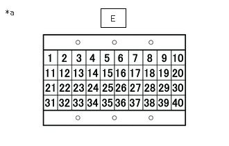
| *a | Signal Check Harness No. 2 Lead Connector |
Connect the signal check harness No. 2 to the DCU (emission control ECU assembly) vehicle side harness. (Do not connect the harness to the DCU (emission control ECU assembly).)
Measure the resistance according to the value(s) in the table below.
- Standard Resistance:
Tester Connection Condition Specified Condition E-6 (UIV+) - E-7 (UIV-) Ignition switch off 17 Ω or less
- Result:
Result Proceed to NG A OK B
A
B
Inspect the urea injector assembly.
Click hereEngine / Hybrid System>N04C-WA (EMISSION CONTROL)>UREA INJECTOR>INSPECTION
- Result:
Proceed to OK NG
OK
NG
Repair or replace the harness or connector.
- Result:
Proceed to NEXT
NEXT
Replace the urea injector assembly.
Click hereEngine / Hybrid System>N04C-WA (EMISSION CONTROL)>UREA INJECTOR>REMOVAL
- Result:
Proceed to NEXT
NEXT
Replace the DCU (emission control ECU assembly).
Click hereEngine / Hybrid System>N04C-WA (EMISSION CONTROL)>UREA PUMP CONTROL ECU>REMOVAL
- Result:
Proceed to NEXT
NEXT
- NOTICE:
-
Injector Refresh takes approximately 40 minutes to complete. Therefore, perform the procedure somewhere the vehicle can be parked for a long period of time.
While checking the refill check tube, refill the urea solution until the tank level is half full or more.
Remove the urea injector assembly from the front exhaust pipe assembly.
Click hereEngine / Hybrid System>N04C-WA (EMISSION CONTROL)>UREA INJECTOR>REMOVAL
- HINT:
- ·
Do not disconnect the urea injector assembly from the urea tube with heater assembly.
·Use a cover, etc., to prevent foreign matter from entering the exhaust pipe.
Prepare a bucket or other receptacle for collecting urea solution from the urea injector assembly.
Connect the GTS to the DLC3.
Turn the ignition switch to ON.
Turn the GTS on.
Enter the following menus: Powertrain / Urea Selective Catalytic Reduction / Utility / Injector Refresh.
Perform the Injector Refresh.
- OK:
Injector Refresh is complete.
- HINT:
-
If the Utility fails, troubleshoot the error message and perform the Utility again.
- Result:
Proceed to NEXT
NEXT
While checking the refill check tube, refill the urea solution until the tank level is half full or more.
Remove the urea injector assembly from the front exhaust pipe assembly.
Click hereEngine / Hybrid System>N04C-WA (EMISSION CONTROL)>UREA INJECTOR>REMOVAL
- HINT:
- ·
Do not disconnect the urea injector assembly from the urea tube with heater assembly.
·Use a cover, etc., to prevent foreign matter from entering the exhaust pipe.
Prepare a bucket or other receptacle for collecting urea solution from the urea injector assembly.
Connect the GTS to the DLC3.
Turn the ignition switch to ON.
Turn the GTS on.
Enter the following menus: Powertrain / Urea Selective Catalytic Reduction / Utility / Reductant Injection / Pattern 1 to 3.
Perform "Pattern 1" to "Pattern 3" and check the urea solution injection volume.
- Standard Value:
Reductant Injection Urea Solution Injection Volume Pattern 3 45 to 55 cc Pattern 2 16 to 24 cc Pattern 1 7 to 13 cc
- Result:
Proceed to OK NG
OK
NG
Repair the urea solution leaks.
- Result:
Proceed to NEXT
NEXT
- Inspection Result:
Result Proceed to When the urea tube with heater assembly is already replaced in step 1, abnormality in other parts can be suspected. Perform the check again. A When the injector refresh is already performed in step 12, replace the urea injector assembly. B When the urea injector assembly and urea tube with heater assembly are already replaced in steps 2 and 8, replace the DCU (emission control ECU assembly). C
A
B
C
Replace the urea tube with heater assembly.
Click hereEngine / Hybrid System>N04C-WA (EMISSION CONTROL)>UREA TUBE>REMOVAL
- Result:
Proceed to NEXT
NEXT
Replace the urea injector assembly.
Click hereEngine / Hybrid System>N04C-WA (EMISSION CONTROL)>UREA INJECTOR>REMOVAL
- Result:
Proceed to NEXT
NEXT
Replace the DCU (emission control ECU assembly).
Click hereEngine / Hybrid System>N04C-WA (EMISSION CONTROL)>UREA PUMP CONTROL ECU>REMOVAL
- Result:
Proceed to NEXT
NEXT
Connect the GTS to the DLC3.
Turn the ignition switch to ON.
Turn the GTS on.
Clear the DTCs.
- NOTICE:
-
Clear the DTCs with the engine stopped, as DTCs cannot be cleared while the engine is running.
Turn the ignition switch off and wait for at least 30 seconds.
- Result:
Proceed to NEXT
NEXT
Drive the vehicle in accordance with the driving pattern described in the Confirmation Driving Pattern.
Connect the GTS to the DLC3.
Turn the ignition switch to ON.
Turn the GTS on.
Enter the following menus: Powertrain / Urea Selective Catalytic Reduction / Trouble Codes.
Read the DTCs.
- OK:
DTCs are not output
- Result:
Proceed to NEXT
NEXT