AIR CONDITIONING FRONT HEATER UNIT INSTALLATION
CAUTION / NOTICE / HINT
- HINT:
- ·
Use the same procedure for LHD and RHD vehicles.
·The procedure listed below is for RHD vehicles.
·A bolt without a torque specification is shown in the standard bolt chart.
Click hereGeneral>SPECIFICATIONS>STANDARD BOLT>SPECIFIED TORQUE FOR STANDARD BOLTS
PROCEDURE

 87210H
1.INSTALL AIR DAMPER CASE ASSEMBLY
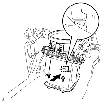
| *1 | Air Damper Case Assembly |
| *a | Vehicle Side Mounting Surface |
Install the air damper case assembly to the vehicle in the direction of the arrow shown in the illustration.
Install the 2 bolts.
2.CONNECT RELAY BLOCK
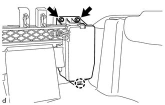
Attach the claw to connect the relay block.
Install the 2 bolts.
85330
3.INSTALL WINDSHIELD WASHER JAR ASSEMBLY
87110
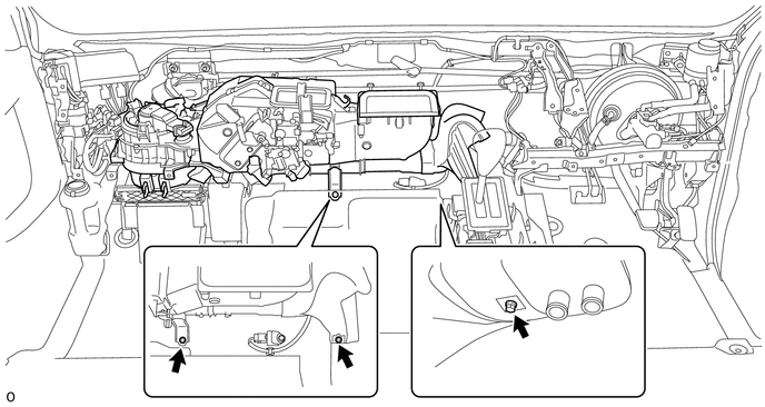
4.INSTALL HEATER ASSEMBLY
Install the heater assembly with the 3 bolts.
55330B
5.INSTALL INSTRUMENT PANEL REINFORCEMENT ASSEMBLY
Install the instrument panel reinforcement assembly with the 14 bolts.
- Torque:
- Bolt A : 20 N*m (204 kgf*cm, 15 ft.*lbf)
Install the 4 screws.
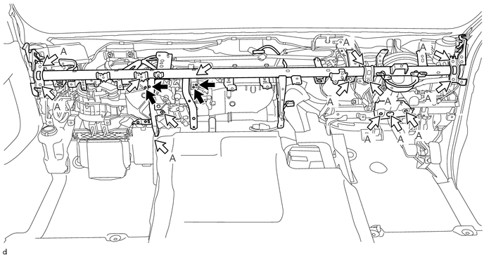

|
Screw | 
|
Bolt |
82141
6.CONNECT INSTRUMENT PANEL WIRE
for RHD:
Attach each clamp to connect the instrument panel wire from the instrument panel reinforcement assembly.
Connect each connector.
Install the bolts and 3 nuts.
Install the 4 ground wires with the 4 bolts.
- Torque:
- 9.5 N*m (97 kgf*cm, 84 in.*lbf)
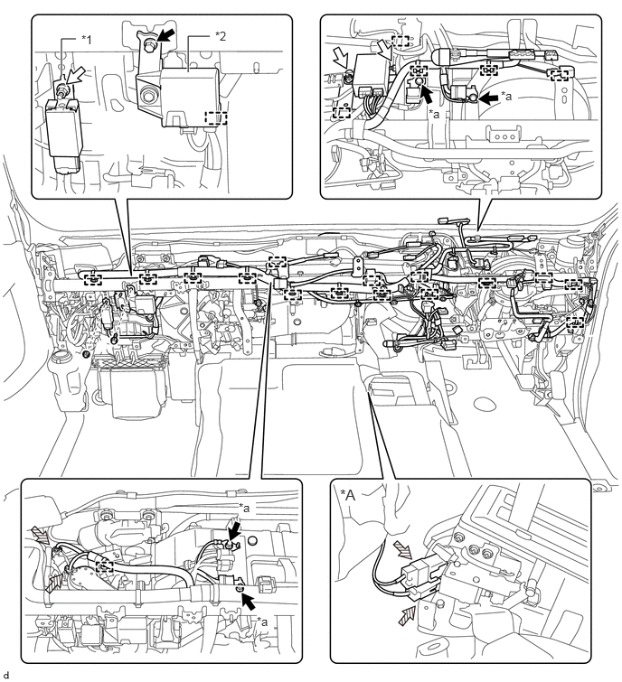
| *A | for Automatic Transmission | - | - |
| *1 | Door Control Relay | *2 | Air Conditioner Amplifier Assembly |
| *a | Ground Wire | - | - |
|
|
Bolt |
|
Nut |

|
Connector | - | - |
for LHD:
Attach each clamp to connect the instrument panel wire from the instrument panel reinforcement assembly.
Connect each connector.
Install the bolts and 4 nuts.
Install the 4 ground wires with the 4 bolts.
- Torque:
- 9.5 N*m (97 kgf*cm, 84 in.*lbf)
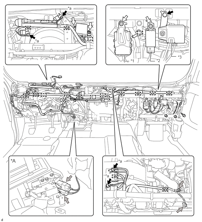
| *A | for Automatic Transmission | - | - |
| *1 | Network Gateway ECU | *2 | Door Control Relay |
| *3 | Air Conditioner Amplifier Assembly | - | - |
| *a | Ground Wire | - | - |
|
|
Bolt |
|
Nut |
|
|
Connector | - | - |
55086A
7.INSTALL HEATER TO REGISTER CENTER DUCT SUB-ASSEMBLY
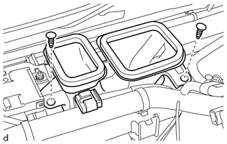
Install the heater to register center duct sub-assembly with the 2 clips.
8.INSTALL NO. 1 INSTRUMENT PANEL BRACE SUB-ASSEMBLY
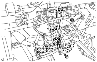
| *a | Hook |
Attach the hook and temporarily install the No. 1 instrument panel brace sub-assembly.
Install the No. 1 instrument panel brace sub-assembly with the nut and bolt.
- Torque:
- 20 N*m (204 kgf*cm, 15 ft.*lbf)
Attach the each clamp.
Attach the 2 claws.
9.INSTALL INSTRUMENT PANEL REINFORCEMENT PANEL BRACE
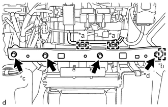
| *a | Clamp |
| *b | Guide |
| *c | Bolt A |
| *d | Bolt B |
Attach the guide to install the instrument panel reinforcement panel brace.
Install the 4 bolts.
- Torque:
- Bolt A : 20 N*m (204 kgf*cm, 15 ft.*lbf)
- Bolt B : 20 N*m (204 kgf*cm, 15 ft.*lbf)
- HINT:
-
Bolt A and bolt B have different lengths.
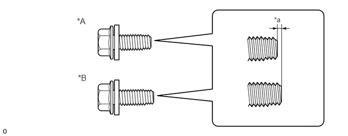 1.583,0.333 1.896,0.583 0.313,0.25 12 false *A 1.604,1.5 1.917,1.75 0.313,0.25 12 false *B 5.646,0.323 5.958,0.521 0.313,0.198 10 false *a
*A Bolt A *B Bolt B *a 1.5mm - -
Attach the 2 clamps.
89539E
10.INSTALL ECU BRACKET
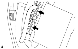
Connect each connector.
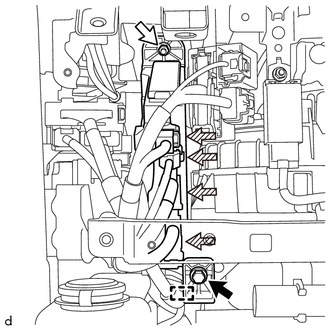
|
|
Bolt |
|
|
Nut |
|
|
Connector |
Connect each connector and attach the wire harness clamp.
Install the ECU bracket with the nut and the bolt.
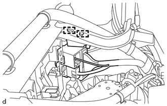
Attach the 2 wire harness clamps.
11.INSTALL STEERING COLUMN ASSEMBLY
12.INSTALL INSTRUMENT PANEL ASSEMBLY
87245A
13.CONNECT HEATER WATER INLET HOSE A
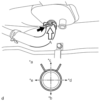
| *a | View A |
| *b | Front of Vehicle |
| *c | Rear of Vehicle |
| *d | Right of Vehicle |
| *e | Left of Vehicle |
Slide the clamp and connect the heater water inlet hose A to the heater assembly.
- NOTICE:
-
Do not apply excessive force to the heater water inlet hose A.
87246A
14.CONNECT HEATER WATER OUTLET HOSE A
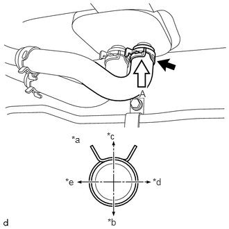
| *a | View A |
| *b | Front of Vehicle |
| *c | Rear of Vehicle |
| *d | Right of Vehicle |
| *e | Left of Vehicle |
Slide the clamp and connect the heater water outlet hose A to the heater assembly.
- NOTICE:
-
Do not apply excessive force to the heater water outlet hose A.
17940D
15.INSTALL INTERCOOLER ASSEMBLY (w/ Intercooler)
for N04C-UH:
Click hereEngine / Hybrid System>N04C-UH (INTAKE)>INTERCOOLER>INSTALLATION
for N04C-VL:
Click hereEngine / Hybrid System>N04C-VL (INTAKE)>INTERCOOLER>INSTALLATION
for N04C-VQ:
Click hereEngine / Hybrid System>N04C-VQ (INTAKE)>INTERCOOLER>INSTALLATION
for N04C-WA:
Click hereEngine / Hybrid System>N04C-WA (INTAKE)>INTERCOOLER>INSTALLATION
16.ADD ENGINE COOLANT (for 1HZ)
17.ADD ENGINE COOLANT (for 2TR-FE)
18.ADD ENGINE COOLANT (for N04C-UH, N04C-VL, N04C-VQ, N04C-WA)
for N04C-UH:
Click hereEngine / Hybrid System>N04C-UH (COOLING)>COOLANT>REPLACEMENT
for N04C-VL:
Click hereEngine / Hybrid System>N04C-VL (COOLING)>COOLANT>REPLACEMENT
for N04C-VQ:
Click hereEngine / Hybrid System>N04C-VQ (COOLING)>COOLANT>REPLACEMENT
for N04C-WA:
Click hereEngine / Hybrid System>N04C-WA (COOLING)>COOLANT>REPLACEMENT
19.INSPECT FOR ENGINE COOLANT LEAK (for 1HZ)
20.INSPECT FOR ENGINE COOLANT LEAK (for 2TR-FE)
21.INSPECT FOR ENGINE COOLANT LEAK (for N04C-UH, N04C-VL, N04C-VQ, N04C-WA)
for N04C-UH:
Click hereEngine / Hybrid System>N04C-UH (COOLING)>COOLANT>REPLACEMENT
for N04C-VL:
Click hereEngine / Hybrid System>N04C-VL (COOLING)>COOLANT>REPLACEMENT
for N04C-VQ:
Click hereEngine / Hybrid System>N04C-VQ (COOLING)>COOLANT>REPLACEMENT
for N04C-WA:
Click hereEngine / Hybrid System>N04C-WA (COOLING)>COOLANT>REPLACEMENT
52119A
22.INSTALL FRONT BUMPER COVER
w/ Snorkel Air Cleaner:
Click hereVehicle Interior>EXTERIOR>FRONT BUMPER (w/ Snorkel Air Cleaner)>INSTALLATION
w/o Snorkel Air Cleaner:
Click hereVehicle Interior>EXTERIOR>FRONT BUMPER(w/o Snorkel Air Cleaner)>INSTALLATION