N04C-VL ENGINE MECHANICAL CYLINDER HEAD REMOVAL
PROCEDURE

 16400
1.REMOVE RADIATOR ASSEMBLY
17201
2.REMOVE TURBOCHARGER SUB-ASSEMBLY
23670
3.REMOVE INJECTOR ASSEMBLY
26100
4.REMOVE VENTURI ASSEMBLY
16577C
5.REMOVE RADIATOR PIPE
87246B
6.DISCONNECT OUTLET HEATER WATER HOSE B
87245B
7.DISCONNECT INLET HEATER WATER HOSE B
87208L
8.REMOVE WATER PIPE SUB-ASSEMBLY
16206B
9.REMOVE NO. 3 WATER BY-PASS PIPE SUB-ASSEMBLY
16206
10.REMOVE WATER BY-PASS PIPE SUB-ASSEMBLY
27020
11.REMOVE GENERATOR ASSEMBLY
16331
12.REMOVE WATER OUTLET
16331A
13.REMOVE THERMOSTAT
Remove the thermostat from the water outlet housing.
Remove the gasket from the thermostat.
16333
14.REMOVE WATER OUTLET HOUSING
17111
15.REMOVE INTAKE MANIFOLD
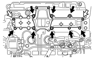
Remove the 8 bolts, 2 nuts and the intake manifold.

|
Bolt |

|
Nut |
17141
16.REMOVE EXHAUST MANIFOLD
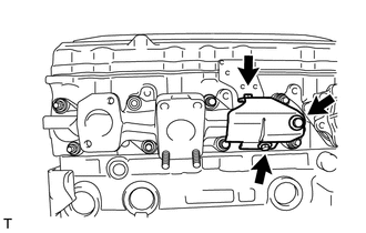
Remove the 3 bolts and exhaust manifold heat insulator.
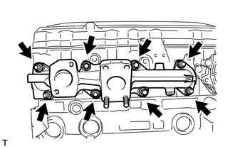
Remove the 8 nuts, 4 spacers, 4 collars and the exhaust manifold.
Remove the 4 exhaust manifold gaskets.
17.SET NO. 1 CYLINDER TO TDC/COMPRESSION
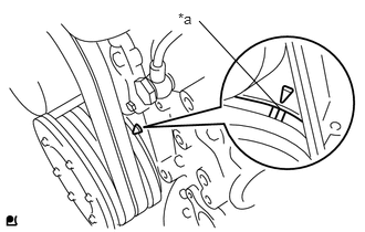
Turn the crankshaft pulley until the groove of the crankshaft damper and the timing mark on the timing gear are aligned.
| *a | Timing Mark |
- HINT:
- ·
Make sure that there is free play in the No. 1 cylinder rocker arms and there is no free play in the No. 4 cylinder rocker arms.
·If not, turn the crankshaft 1 revolution (360°) to set the No. 1 cylinder to TDC/compression.
13901
18.REMOVE NO. 1 VALVE ROCKER SHAFT SUB-ASSEMBLY
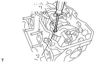
Loosen the lock nuts at the top of the rocker arms and wind up the adjusting screws completely.
| *1 | Adjusting Screw |
| *2 | Lock Nut |
- NOTICE:
-
If the adjusting screws are left unwound, the rocker shaft may bend when the rocker arm support bolts are loosened.
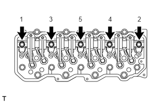
Loosen the 5 rocker arm support bolts in the order shown in the illustration.
Remove the No. 1 valve rocker shaft sub-assembly.
13781
19.REMOVE VALVE PUSH ROD
Remove the valve push rod.
- HINT:
-
Organize the parts so that each part location can be remembered for reassembly.
13819
20.REMOVE VALVE BRIDGE
Remove the valve bridge.
- HINT:
-
Organize the parts so that each part location can be remembered for reassembly.
11101
21.REMOVE CYLINDER HEAD SUB-ASSEMBLY
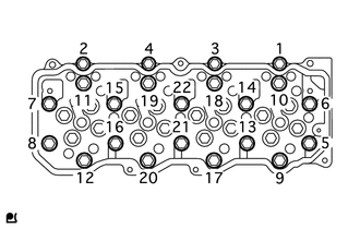
Remove the 22 cylinder head bolts in 3 steps in the sequence shown in the illustration.
Lift and remove the cylinder head sub-assembly from the cylinder block.
11115
22.REMOVE CYLINDER HEAD GASKET
Remove the cylinder head gasket.
13751
23.REMOVE VALVE LIFTER
Remove the valve lifter.
- HINT:
-
Organize the parts so that each part location can be remembered for reassembly.