N04C-VL FUEL FUEL INJECTOR INSTALLATION
PROCEDURE

 23670
1.INSTALL INJECTOR ASSEMBLY
- NOTICE:
-
 2.344,1.688 2.552,0.76 true 2.24,1.708 2.5,1.969 0.26,0.26 10 false *1
-
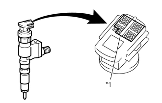
Register the injector compensation code of a new fuel injector in the ECM when replacing the fuel injector. Register the injector compensation code in advance so that the fuel injector can be installed in the correct position.
-
(Click hereEngine / Hybrid System>N04C-VL (ENGINE CONTROL)>ECD SYSTEM>REGISTRATION)
| *1 | Injector Compensation Code |
Install 4 new injection nozzle seats to the cylinder head.
Apply a light amount of clean engine oil to 4 new O-rings.
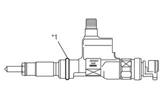
Install an O-ring to each injector assembly as shown in the illustration.
| *1 | O-ring |
Install a new No. 2 cylinder head cover gasket to each injector assembly.
Insert the 4 injector assemblies into the cylinder head.
- NOTICE:
- ·
Check that the insertion part of the fuel injector has no foreign matter attached.
·When reusing a fuel injector, install the same fuel injector that was removed. Otherwise, it could cause the engine to malfunction.
·Carefully insert the fuel injector so that the O-ring is not caught between the cylinder head and the injector.
·Be sure to prevent foreign matter or water from entering the lines.
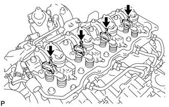
Temporarily install the 4 nozzle holder clamps with the 4 clamp bolts.
- NOTICE:
-
Be sure to install the holder clamps and bolts in their original positions.
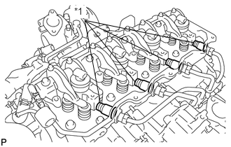
Install new 4 holder seals.
| *1 | Holder Seal |
- NOTICE:
-
Securely insert the tip of the holder seal into the injector assembly.
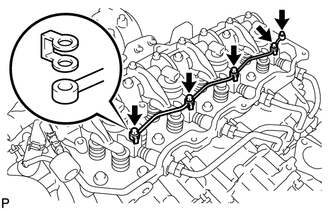
Temporarily install the nozzle leakage pipe through 5 new gaskets by hand with the union bolt and 4 hollow screws.
- NOTICE:
-
Make sure that the hollow screws, union bolt and nozzle leakage pipe assembly are not deformed or damaged.
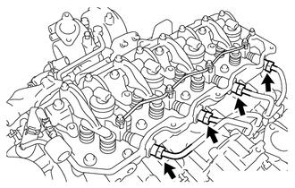
Temporarily tighten the union nuts of injection pipe sub-assemblies No. 1, No. 2, No. 3 and No. 4 by hand.
- NOTICE:
-
If an injector assembly has been replaced, the corresponding injection pipe sub-assembly must also be replaced.
Tighten the 4 nozzle holder clamp bolts.
- Torque:
25 N*m (255 kgf*cm, 18 ft.*lbf)
- NOTICE:
-
After tightening the nozzle holder clamp bolts, check that the injector assembly and the nozzle holder clamp do not interfere with the valve spring.
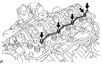
Tighten the 4 hollow screws and union bolt.
- Torque:
13 N*m (130 kgf*cm, 10 ft.*lbf)
- NOTICE:
-
If the nozzle leakage pipe has been tightened to more than the specified torque, replace it with a new one.
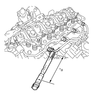
Using a union nut wrench (17 mm), tighten the injection pipe union nuts.
- Torque:
- Specified tightening torque:
35 N*m (357 kgf*cm, 26 ft.*lbf)
| *a | Torque Wrench Fulcrum Length |
- HINT:
- ·
Calculate the torque wrench reading when changing the fulcrum length of the torque wrench.
(Click hereGeneral>INTRODUCTION>REPAIR INSTRUCTION>PRECAUTION)
·When using a union nut wrench (fulcrum length of 30mm (1.1811 in.)) + torque wrench (fulcrum length of 180 mm (7.0866 in.)): 30 N*m (306 kgf*cm, 22 ft.*lbf)
23741B
2.INSTALL INJECTION PIPE CLAMP
Install the 2 injection pipe clamps with the 2 nuts. Tighten the 2 nuts until the clamp's edges make contact with the engine side clamp's edges.
11202D
3.INSTALL NO. 2 CYLINDER HEAD COVER SUB-ASSEMBLY
12601B
4.INSTALL NO. 1 ENGINE COVER SUB-ASSEMBLY
58701A
5.INSTALL FRONT ENGINE SERVICE COVER PANEL SUB-ASSEMBLY
33503F
6.INSTALL FLOOR SHIFT SHIFT LEVER SUB-ASSEMBLY
33820B
7.CONNECT TRANSMISSION CONTROL CABLE ASSEMBLY
58286
8.INSTALL NO. 1 SHIFT AND SELECT LEVER BOOT
9.BLEED AIR FROM FUEL SYSTEM
10.REGISTRATION INJECTOR COMPENSATION CODE
Register the injector compensation code.
(Click hereEngine / Hybrid System>N04C-VL (ENGINE CONTROL)>ECD SYSTEM>REGISTRATION)
11.CHECK FOR INJECTOR COMPENSATION CODE
12.INSPECT FOR FUEL LEAK
13.INSPECT FOR COOLANT LEAK
14.INSPECT FOR OIL LEAK
58534A
15.INSTALL TRANSMISSION COVER MAT
33504F
16.INSTALL SHIFT KNOB
58420
17.INSTALL NO. 2 ENGINE SERVICE HOLE COVER ASSEMBLY
58521D
18.INSTALL ENGINE SERVICE HOLE COVER MAT
58734B
19.INSTALL REAR ENGINE SERVICE COVER WEATHERSTRIP
58410
20.INSTALL ENGINE SERVICE HOLE COVER