N04C-VJ ENGINE CONTROL ECD SYSTEM P0093 Fuel System Leak Detected - Large Leak
DESCRIPTION
The fuel pressure sensor is attached to the common rail assembly, and converts fuel pressure to an electrical signal that is output to the ECM.
The ECM controls the injection or supply pump assembly (suction control valve) based on signals from the fuel pressure sensor. As a result, the fuel pressure in the common rail assembly is maintained at the target pressure setting.
| DTC No. | Detection Item | DTC Detection Condition | Trouble Area | MIL | Memory |
|---|---|---|---|---|---|
| P0093 | Fuel System Leak Detected - Large Leak | Engine speed is 1500 rpm or higher.
The fuel pressure drops before and after fuel injection greater than the malfunction judgment valueThe predetermined amount of times. (0.2 seconds or more in real time) (1 trip detection logic) |
·
Wire harness or connector ·
Fuel leak (injection or supply pup assembly to common rail assembly to injector assembly) ·
Injector assembly ·
Injection or supply pump assembly (suction control valve) ·
Common rail assembly ·
ECM |
Comes on | DTC stored |
CONFIRMATION DRIVING PATTERN
| DTC No. | DTC Detection Drive Pattern |
|---|---|
| P0093 | Start the engine and warm it up.
Fully depress the accelerator pedal for 5 seconds and then release it. (*A) Fully depress the accelerator pedal and release the pedal after reaching 2000 rpm. (*B) Perform the above procedures (*A) and (*B) 5 times. |
WIRING DIAGRAM
Refer to DTC P0088 (Click hereEngine / Hybrid System>N04C-VJ (ENGINE CONTROL)>ECD SYSTEM>P0088).
CAUTION / NOTICE / HINT
- NOTICE:
- ·
After replacing the ECM, the new ECM needs registration (Click here Engine / Hybrid System>N04C-VJ (ENGINE CONTROL)>ECD SYSTEM>REGISTRATION) and initialization (Click here Engine / Hybrid System>N04C-VJ (ENGINE CONTROL)>ECD SYSTEM>INITIALIZATION).
·After replacing the injection or supply pup assembly, the ECM needs initialization (Click here Engine / Hybrid System>N04C-VJ (ENGINE CONTROL)>ECD SYSTEM>INITIALIZATION).
·After replacing the injector assembly, the ECM needs registration (Click here Engine / Hybrid System>N04C-VJ (ENGINE CONTROL)>ECD SYSTEM>REGISTRATION).
- HINT:
-
Read freeze frame data using the GTS. Freeze frame data records the engine condition when malfunctions are detected. When troubleshooting, freeze frame data can help determine if the vehicle was moving or stationary, if the engine was warmed up or not, and other data from the time the malfunction occurred.
PROCEDURE
Connect the GTS to the DLC3.
Turn the ignition switch to ON.
Turn the GTS on.
Enter the following menus: Powertrain / Engine and ECT / DTC.
Read DTCs.
- Result:
Result Proceed to DTC P0087, P0190, P0192, P0193, P0200, P0201, P0202, P0203, P0204, P062D, P0088, P0627 or P1229 is not output A DTC P0087, P0190, P0192, P0193, P0200, P0201, P0202, P0203, P0204, P062D, P0088, P0627 or P1229 is output B
A
B
Connect the GTS to the DLC3.
Start the engine.
Turn the GTS on.
Enter the following menus: Powertrain / Engine and ECT / Active Test / Test the Fuel Leak.
Visually check the injection or supply pump assembly, injector assembly and fuel line located between the injection or supply pump assembly and common rail assembly for fuel leaks and fuel pressure leaks. Also, perform the same check on the fuel line between the common rail assembly and the injector assembly.
- HINT:
-
There may be fuel leaks inside the components, such as the injection or supply pump assembly.
- OK:
No leak.
- Result:
Proceed to OK NG
OK
NG
Inspect the suction control valve.
Click hereEngine / Hybrid System>N04C-VJ (FUEL)>FUEL SUPPLY PUMP>INSPECTION
- Result:
Proceed to OK NG
OK
NG
Connect the GTS to the DLC3.
Start the engine.
Turn the GTS on.
Enter the following menus: Powertrain / Engine and ECT / Data List / Target Pump SCV Current.
Read the value.
- Standard:
Engine Speed Result Idling 1350 to 2200 mA
- Result:
Proceed to OK NG
OK
NG
Connect the GTS to the DLC3.
Start the engine.
Turn the GTS on.
Enter the following menus: Powertrain / Engine and ECT / Data List / Fuel Press, Target Common Rail Pressure.
Check that the internal fuel pressure of the common rail is within the specification below.
- Standard:
Item Engine Speed Specified Condition Fuel Press Idling Approximately 20000 to 30000 kPa 2800rpm Approximately 110000 to 120000 kPa Target Common Rail Pressure Idling Difference from target common rail pressure within 5000 kPa 2800rpm Difference from target common rail pressure within 5000 kPa
- NOTICE:
-
The fuel pressure is listed here as a standard value, but the standard value will vary depending on the vehicle condition and model.
-
When judging the fuel pressure, check that the common rail target fuel pressure and fuel pressure follow reliably with the accelerator position and engine speed at a constant setting.
-
However, the common rail target fuel pressure and fuel pressure will not follow immediately after operating the accelerator pedal.
- Result:
Result Proceed to NG A OK B
A
B
Check the wire harness and connector.
Disconnect the fuel pressure sensor connector.
Disconnect the ECM connector.
Measure the resistance according to the value(s) in the table below.
- Standard Resistance:
Standard Resistance Condition Specified Condition B104-13(VC) - B93-1(VC1) Always Below 1 Ω B105-16(PCR1) - B93-2(PCR1) Always Below 1 Ω B104-14(E2) - B93-3(E1) Always Below 1 Ω B105-14(E21) - B93-4(E2) Always Below 1 Ω B105-2(PCR2) - B93-5(PCR2) Always Below 1 Ω B105-13(VC2) - B93-6(VC2) Always Below 1 Ω B104-13(VC) or B93-1(VC1) - Body ground Always 10 kΩ or higher B105-16(PCR1) or B93-2(PCR1) - Body ground Always 10 kΩ or higher B104-14(E2) or B93-3(E1) - Body ground Always 10 kΩ or higher B105-14(E21) or B93-4(E2) - Body ground Always 10 kΩ or higher B105-2(PCR2) or B93-5(PCR2) - Body ground Always 10 kΩ or higher B105-13(VC2) or B93-6(VC2) Always 10 kΩ or higher
- Result:
Proceed to OK NG
OK
NG
Connect the GTS to the DLC3.
Turn the ignition switch to ON.
Turn the GTS on.
Enter the following menus: Powertrain / Engine and ECT / Data List / Fuel Press.
Wiggle the fuel pressure sensor connector and check that the fuel pressure reading does not change.
- OK:
The fuel pressure reading does not change.
- Result:
Proceed to OK NG
OK
NG
Perform initialization (Click hereEngine / Hybrid System>N04C-VJ (ENGINE CONTROL)>ECD SYSTEM>INITIALIZATION).
- Result:
Proceed to NEXT
NEXT
Check the wire harness and connector.
Disconnect the suction control valve connector.
Disconnect the ECM connector.
Measure the resistance according to the value(s) in the table below.
- Standard Resistance:
Standard Resistance Condition Specified Condition B103-23 (PCV+) - B52-1 (SCV+) Always Below 1 Ω B103-12 (PCV-) - B52-2 (SCV-) Always Below 1 Ω B103-23 (PCV+) or B52-1 (SCV+) - Body ground Always 10 kΩ or higher B103-12 (PCV-) or B52-2 (SCV-) - Body ground Always 10 kΩ or higher
- Result:
Proceed to OK NG
OK
NG
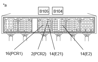
| *a | Component with harness connected
(ECM) |
Start the engine.
Measure the voltage according to the value(s) in the table below.
- Standard Voltage:
Tester Connection Condition Specified Condition B105-16(PCR1) - B104-14(E2) Idling 1.6 to 2.0 V B105-16(PCR1) - B104-14(E2) Idling 1.1 to 1.5 V
- Result:
Proceed to OK NG
OK
NG
Replace the injector assembly.
Click hereEngine / Hybrid System>N04C-VJ (FUEL)>FUEL INJECTOR>REMOVAL
- Result:
Proceed to NEXT
NEXT
Connect the GTS to the DLC3.
Clear the DTCs. (Click hereEngine / Hybrid System>N04C-VJ (ENGINE CONTROL)>ECD SYSTEM>DTC CHECK / CLEAR)
- Result:
Proceed to NEXT
NEXT
Connect the GTS to the DLC3.
Fully warm up the engine.
Allow the engine to idle for 5 minutes or more.
Turn the GTS on.
Clear the DTCs.
Enter the following menus: Powertrain / Engine and ECT / DTC.
Read the DTCs.
- Result:
Result Proceed to P0088, P0627 or P1229 is output A P0088, P0627 or P1229 is not output B
A
B
Check the fuel injection system.
Click hereEngine / Hybrid System>N04C-VJ (ENGINE CONTROL)>ECD SYSTEM>Fuel Injection System
- Result:
Proceed to OK NG
OK
NG