N04C-VJ ENGINE CONTROL ECD SYSTEM Exhaust Brake System Circuit
WIRING DIAGRAM
Refer to DTC P1674 (Click hereEngine / Hybrid System>N04C-VJ (ENGINE CONTROL)>ECD SYSTEM>P1674).
CAUTION / NOTICE / HINT
- NOTICE:
- ·
After replacing the ECM, the new ECM needs registration (Click hereEngine / Hybrid System>N04C-VJ (ENGINE CONTROL)>ECD SYSTEM>REGISTRATION) and initialization (Click hereEngine / Hybrid System>N04C-VJ (ENGINE CONTROL)>ECD SYSTEM>INITIALIZATION).
·Inspect the fuses for circuits related to this system before performing the followinginspection procedure.
PROCEDURE
Connect the GTS to the DLC3.
Turn the ignition switch to ON.
Turn the GTS on.
Clear the DTCs (Click hereEngine / Hybrid System>N04C-VJ (ENGINE CONTROL)>ECD SYSTEM>DTC CHECK / CLEAR).
Turn the ignition switch off and wait for 30 seconds or more.
Turn the ignition switch to ON and wait for 1 second or more.
Enter the following menus: Powertrain / Engine and ECT / Trouble Codes.
Read the DTCs.
- HINT:
-
If a DTC is output, the exhaust brake system may be prohibited.
- Result:
Result Proceed to DTC P1674 is output A DTC is not output B
B
A
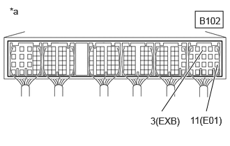
| *a | Component with harness connected
(ECM) |
Turn the ignition switch to ON.
Measure the voltage according to the value(s) in the table below.
- Standard Voltage:
Tester Connection Switch Condition Specified Condition B102-3 (EXB) - B102-11 (E01) Exhaust brake operating 11 to 14 V
- HINT:
- Exhaust brake operation conditions·
Exhaust brake switch ON
·Accelerator pedal not operated
·At or above the specified vehicle speed (3 km/h or higher)
·ABS not operating
- Result:
Proceed to OK NG
OK
NG
Inspect the exhaust brake with bracket solenoid assembly.
Click hereBrake>EXHAUST BRAKE>EXHAUST BRAKE RETARDER SOLENOID>INSPECTION
- Result:
Proceed to OK NG
OK
NG
Inspect the exhaust retarder assembly
- Result:
Result Proceed to Exhaust retarder assembly is normal A The butterfly valve is not fully open B The needle drops when a vacuum is applied C The needle does not drop, but clearance is outside the standard value D
- HINT:
-
If checking shows a normal result, perform troubleshooting for black smoke(Click hereEngine / Hybrid System>N04C-VJ (ENGINE CONTROL)>ECD SYSTEM>Black Smoke Emitted).
A
B
C
D
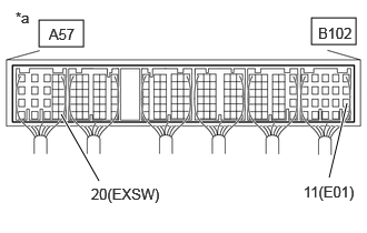
| *a | Component with harness connected
(ECM) |
Turn the ignition switch to ON.
Measure the voltage according to the value(s) in the table below.
- Standard Voltage:
Tester Connection Switch Condition Specified Condition A57-20 (EXSW) - B102-11 (E01) Exhaust brake switch position ON 11 to 14 V Exhaust brake switch position OFF 0 to 2 V
- Result:
Proceed to OK NG
OK
NG
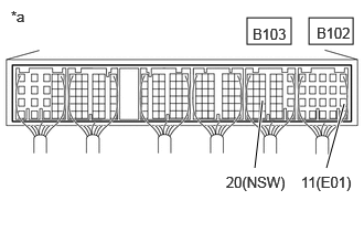
| *a | Component with harness connected
(ECM) |
Turn the ignition switch to ON.
Measure the voltage according to the value(s) in the table below.
- Standard Voltage:
Tester Connection Switch Condition Specified Condition B103-20 (NSW) - B102-11 (E01) Ignition switch ON, shift position is not neutral 11 to 14 V Ignition switch ON, shift position is neutral 0 to 2 V
- Result:
Proceed to OK NG
OK
NG
Inspect the park/neutral position switch assembly (Click hereDrivetrain>A861E (AUTOMATIC TRANSMISSION / TRANSAXLE)>PARK / NEUTRAL POSITION SWITCH>ON-VEHICLE INSPECTION).
- Result:
Proceed to OK NG
OK
NG