N04C-VJ ENGINE CONTROL ECD SYSTEM Black Smoke Emitted
WIRING DIAGRAM
Refer to DTC P0087 (Click hereEngine / Hybrid System>N04C-VJ (ENGINE CONTROL)>ECD SYSTEM>P0087).
Refer to DTC P0095 (Click hereEngine / Hybrid System>N04C-VJ (ENGINE CONTROL)>ECD SYSTEM>P0095).
Refer to DTC P0107 (Click hereEngine / Hybrid System>N04C-VJ (ENGINE CONTROL)>ECD SYSTEM>P0107).
Refer to DTC P0112 (Click hereEngine / Hybrid System>N04C-VJ (ENGINE CONTROL)>ECD SYSTEM>P0112).
Refer to DTC P0115 (Click hereEngine / Hybrid System>N04C-VJ (ENGINE CONTROL)>ECD SYSTEM>P0115).
Refer to DTC P0201 (Click hereEngine / Hybrid System>N04C-VJ (ENGINE CONTROL)>ECD SYSTEM>P0201).
Refer to DTC P2120 (Click hereEngine / Hybrid System>N04C-VJ (ENGINE CONTROL)>ECD SYSTEM>P2120).
CAUTION / NOTICE / HINT
- NOTICE:
- ·
After replacing the ECM, the new ECM needs registration (Click here Engine / Hybrid System>N04C-VJ (ENGINE CONTROL)>ECD SYSTEM>REGISTRATION and initialization (Click here Engine / Hybrid System>N04C-VJ (ENGINE CONTROL)>ECD SYSTEM>INITIALIZATION).
·After replacing the injection or supply pump assembly, the ECM needs initialization (Click here Engine / Hybrid System>N04C-VJ (ENGINE CONTROL)>ECD SYSTEM>INITIALIZATION).
·After replacing the injector assembly, the ECM needs registration (Click here Engine / Hybrid System>N04C-VJ (ENGINE CONTROL)>ECD SYSTEM>REGISTRATION).
- HINT:
-
Specified values in the following troubleshooting flowchart are for reference only. Variations in the Data List values may occur depending on the measuring conditions or the vehicle's age. Do not assume the vehicle is normal when the Data List outputs standard values. There may be concealed factors of the malfunction.
PROCEDURE
Connect the GTS to the DLC3.
Turn the ignition switch to ON.
Turn the GTS on.
Enter the following menus: Powertrain / Engine and ECT / DTC.
Read the DTCs.
- Result:
Result Proceed to No output A DTCs related to engine B
A
B
Check that the ID code is registered correctly.
Click hereEngine / Hybrid System>N04C-VJ (ENGINE CONTROL)>ECD SYSTEM>REGISTRATION
- Result:
Proceed to OK NG
OK
NG
Connect the GTS to the DLC3.
Start the engine.
Turn the GTS on.
Enter the following menus: Powertrain / Engine and ECT / Data List.
Enter the following menus in order and read the values.
Fuel Press
Injection Volume
Main Injection Period
Pilot 1 Injection Period
Pilot 2 Injection Period
Main Injection Timing
Injection Feedback Val #1 to #4
- NOTICE:
- ·
It is difficult to indicate a clear standard value (judgment value) for Data List value since there is significant variation due to minor difference of measurement, difference in the measuring environment, aging variation of the vehicle, etc.
It is possible that a malfunction may be present even if measured values are within the standard range.
·In the event of a problem with intricate symptoms such as hesitation and rough idling, collect sample data from another vehicle of the same model operating under identical conditions in order to reach an overall judgment by comparing all the items in the Data List.
·The actual common rail pressure is listed here as a standard value, but the standard value will vary depending on the vehicle condition and model.
When judging the fuel pressure, check that the target common rail pressure and actual common rail pressure follow reliably with the accelerator position and engine speed at a constant setting.
However, the target common rail pressure and actual common rail pressure will not follow immediately after operating the accelerator pedal.
- Standard:
Item Engine Speed* Reference Value Fuel Press Idling 20000 to 30000 kPa 2800 rpm 110000 to 120000 kPa Injection Volume Idling 5 to 12 mm3/st 2800 rpm 9 to 17 mm3/st Main Injection Period Idling 500 to 1000 μs Pilot 1 Injection Period Idling 0 to 500 μs Pilot 2 Injection Period Idling 0 to 600 μs Main Injection Timing Idling -1 to 1°CA 2000 rpm -5 to 3°CA 3000 rpm -6 to 2°CA Injection Feedback Val #1 Idling -7.0 to 7.0 mm3/st Injection Feedback Val #2 Idling -7.0 to 7.0 mm3/st Injection Feedback Val #3 Idling -7.0 to 7.0 mm3/st Injection Feedback Val #4 Idling -7.0 to 7.0 mm3/st
- HINT:
-
*: The shift lever should be in the neutral position, and the A/C switch and all accessory switches should be OFF.
- Result:
Proceed to OK NG
OK
NG
- HINT:
-
If the exhaust gas contains excessive black smoke, perform the following operations:
Accelerate the engine speed to the maximum rpm with no load 20 times.
Check the volume of black smoke in the exhaust gas.
- Result:
Result Proceed to Black smoke is not present A Black smoke remains in the exhaust gas B
- HINT:
-
Soot deposits in the exhaust system may cause excessive black smoke.
A
B
Inspect the engine condition (Click here Engine / Hybrid System>N04C-VJ (EMISSION CONTROL)>EMISSION CONTROL SYSTEM>ON-VEHICLE INSPECTION).
- Result:
Proceed to OK NG
OK
NG
Inspect the exhaust retarder assembly.
- Result:
Proceed to OK NG
OK
NG
Connect the GTS to the DLC3.
Turn the ignition switch to ON and turn the GTS on.
Enter the following menus: Powertrain / Engine and Transmission / Data List / Engine Speed and Mass Air Flow Sensor.
Start the engine and read the value when 30 seconds has elapsed.
- Standard:
Engine Speed Mass Air Flow Sensor Idling 4 to 15 gm/sec 3000 rpm (without load) 80 to 90 gm/sec
- Result:
Proceed to OK NG
OK
NG
Check the turbocharger pressure (Click here Engine / Hybrid System>N04C-VJ (INTAKE)>INTAKE SYSTEM>ON-VEHICLE INSPECTION).
- Result:
Proceed to OK NG
OK
NG
Replace the injector assembly.
Click hereEngine / Hybrid System>N04C-VJ (FUEL)>FUEL INJECTOR>REMOVAL
Start the engine and check if the malfunction disappears.
- Result:
Proceed to OK NG
OK
NG
Connect the GTS to the DLC3.
Start the engine.
Turn the GTS on.
Enter the following menus: Powertrain / Engine and ECT / Data List.
Enter the following menus in order and read the values.
Fuel Press
Injection Volume
Main Injection Period
Pilot 1 Injection Period
Pilot 2 Injection Period
Main Injection Timing
Injection Feedback Val #1 to #4
- NOTICE:
- ·
It is difficult to indicate a clear standard value (judgment value) for Data List value since there is significant variation due to minor difference of measurement, difference in the measuring environment, aging variation of the vehicle, etc.
It is possible that a malfunction may be present even if measured values are within the standard range.
·In the event of a problem with intricate symptoms such as hesitation and rough idling, collect sample data from another vehicle of the same model operating under identical conditions in order to reach an overall judgment by comparing all the items in the Data List.
·The actual common rail pressure is listed here as a standard value, but the standard value will vary depending on the vehicle condition and model.
When judging the fuel pressure, check that the target common rail pressure and actual common rail pressure follow reliably with the accelerator position and engine speed at a constant setting.
However, the target common rail pressure and actual common rail pressure will not follow immediately after operating the accelerator pedal.
- Standard:
Item Engine Speed* Reference Value Fuel Press Idling 20000 to 30000 kPa 2800 rpm 110000 to 120000 kPa Injection Volume Idling 5 to 12 mm3/st 2800 rpm 9 to 17 mm3/st Main Injection Period Idling 500 to 1000 μs Pilot 1 Injection Period Idling 0 to 500 μs Pilot 2 Injection Period Idling 0 to 600 μs Main Injection Timing Idling -1 to 1°CA 2000 rpm -5 to 3°CA 3000 rpm -6 to 2°CA Injection Feedback Val #1 Idling -7.0 to 7.0 mm3/st Injection Feedback Val #2 Idling -7.0 to 7.0 mm3/st Injection Feedback Val #3 Idling -7.0 to 7.0 mm3/st Injection Feedback Val #4 Idling -7.0 to 7.0 mm3/st
- HINT:
-
*: The shift lever should be in the neutral position, and the A/C switch and all accessory switches should be OFF.
- Result:
Proceed to OK NG
OK
NG
Check the cylinder compression pressure (Click here Engine / Hybrid System>N04C-VJ (ENGINE MECHANICAL)>ENGINE>ON-VEHICLE INSPECTION).
- Result:
Proceed to OK NG
OK
NG
Check the wire harness between the injector assembly and injector driver assembly (INJ terminal).
Disconnect the injector assembly connectors.
Disconnect the injector driver assembly connectors.
Measure the resistance according to the value(s) in the table below.
- Standard Resistance:
Tester Connection Condition Specified Condition B98-1(IJ1+) - i1-2 Always Below 1 Ω B95-6(IJ1-) - i1-1 Always Below 1 Ω B98-6(IJ2+) - i2-2 Always Below 1 Ω B95-4(IJ2-) - i2-1 Always Below 1 Ω B98-5(IJ3+) - i3-2 Always Below 1 Ω B95-2(IJ3-) - i3-1 Always Below 1 Ω B95-3(IJ4+) - i4-2 Always Below 1 Ω B95-5(IJ4-) - i4-1 Always Below 1 Ω B98-1(IJ1+) or i1-2 - Body ground Always 10 kΩ or higher B95-6(IJ1-) or i1-1 - Body ground Always 10 kΩ or higher B98-6(IJ2+) or i2-2 - Body ground Always 10 kΩ or higher B95-4(IJ2-) or i2-1 - Body ground Always 10 kΩ or higher B98-5(IJ3+) or i3-2 - Body ground Always 10 kΩ or higher B95-2(IJ3-) or i3-1 - Body ground Always 10 kΩ or higher B95-3(IJ4+) or i4-2 - Body ground Always 10 kΩ or higher B95-5(IJ4-) or i4-1 - Body ground Always 10 kΩ or higher
Reconnect the injector assembly connectors.
Reconnect the injector driver assembly connectors.
- Result:
Proceed to OK NG
OK
NG
- HINT:
-
Use this Active Test to determine the malfunctioning cylinder.
Connect the GTS to the DLC3.
Start the engine.
Turn the GTS on.
Enter the following menus: Powertrain / Engine and ECT / Active Test / Control the Cylinder #1 to #4 Fuel Cut.
- HINT:
- ·
If the engine idle speed does not change when a fuel injector is disabled, the cylinder being tested is malfunctioning.
·If the cylinder being tested is normal, there will be a significant change in idle speed when the fuel injection is stopped for that cylinder.
- Result:
Result Proceed to Engine idling condition becomes unstable A Engine idling condition does not change B
A
B
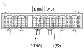
| *a | Component with harness connected
(ECM) |
Start the engine.
Measure the voltage according to the value(s) in the table below.
- Standard Voltage:
Tester Connection Condition Specified Condition B105-9 (THW) - B104-14 (E2) Idling, engine coolant temperature between 70 to 90°C (158 to 194°F) 0.4 to 0.7 V
- Result:
Proceed to OK NG
OK
NG
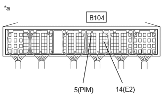
| *a | Component with harness connected
(ECM) |
Turn the ignition switch to ON.
Measure the voltage according to the value(s) in the table below.
- Standard Voltage:
Tester Connection Condition Specified Condition B104-5 (PIM) - B104-14 (E2) Negative pressure of 40 kPa [abs] (300 mmHg, 11.8 in.Hg) applied 0.1 to 0.7 V Open to atmospheric air 101.3 kPa [abs] (760 mmHg, 29.9 in.Hg) applied 0.8 to 1.5 V Positive pressure of 170kPa [abs] (1275 mmHg, 50.2 in.Hg) applied 1.6 to 2.3 V
- Result:
Proceed to OK NG
OK
NG
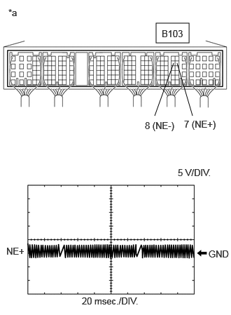
| *a | Component with harness connected
(ECM) |
While idling the engine, check the waveform between the specified terminals of the ECM connector using an oscilloscope.
- HINT:
- ·
The higher the engine speed becomes, the larger the amplitude.
·The higher the engine speed becomes, the shorter the cycle.
·A DTC may be detected due to noise.
- Standard:
Tester Connection Condition Specified Condition B103-7 (NE+) - B103-8 (NE-) Engine idling Correct waveform appears as shown
- Result:
Proceed to OK NG
OK
NG
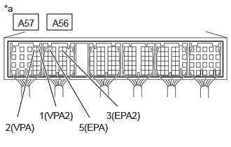
| *a | Component with harness connected
(ECM) |
Turn the ignition switch to ON.
Measure the voltage according to the value(s) in the table below.
- Standard Voltage:
Tester Condition Accelerator Pedal Condition Specified Condition A57-2 (VPA) - A56-5 (EPA) Released 0.6 to 1.0 V Depressed 2.8 to 3.6 V A57-1 (VPA2) - A56-3 (EPA2) Released 1.4 to 1.8 V Depressed 3.6 to 4.4 V
- Result:
Proceed to OK NG
OK
NG
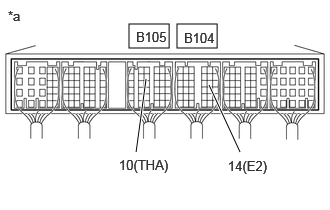
| *a | Component with harness connected
(ECM) |
Start the engine.
Measure the voltage according to the value(s) in the table below.
- Standard Voltage:
Tester Condition Accelerator Pedal Condition Specified Condition B105-10 (THA) - B105-14 (E2) Idling, intake air temperature at 0 to 80°C (32 to 176°F) 0.5 to 3.4 V
- Result:
Proceed to OK NG
OK
NG
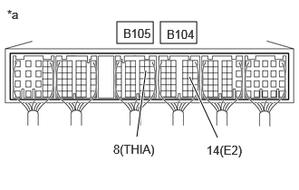
| *a | Component with harness connected
(ECM) |
Start the engine.
Measure the voltage according to the value(s) in the table below.
- Standard Voltage:
Tester Condition Accelerator Pedal Condition Specified Condition B105-8 (THIA) - B104-14 (E2) Idling, intake air temperature at 0 to 80°C (32 to 176°F) 1.0 to 4.4 V
- Result:
Proceed to OK NG
OK
NG
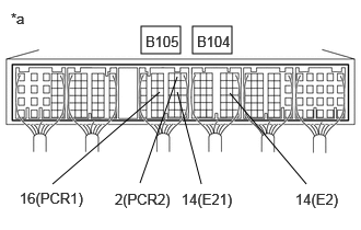
| *a | Component with harness connected
(ECM) |
Start the engine.
Measure the voltage according to the value(s) in the table below.
- Standard Voltage:
Tester Condition Accelerator Pedal Condition Specified Condition B105-16(PCR1) - B104-14(E2) Idling 1.6 to 2.0 V B105-2 (PCR2) - B105-14(E21) Idling 1.1 to 1.5 V
- Result:
Proceed to OK NG
OK
NG
Check the fuel injection system.
Click hereEngine / Hybrid System>N04C-VJ (ENGINE CONTROL)>ECD SYSTEM>Fuel Injection System
Check that the malfunction has disappeared.
- Result:
Result Proceed to Malfunction does not disappear A Malfunction disappears B
A
B
Inspect the engine coolant temperature sensor.
Click hereEngine / Hybrid System>N04C-VJ (ENGINE CONTROL)>ENGINE COOLANT TEMPERATURE SENSOR>INSPECTION
- Result:
Proceed to OK NG
OK
NG
Disconnect the manifold absolute pressure sensor connector.
Disconnect the ECM connectors.
Measure the resistance according to the value(s) in the table below.
- Standard Resistance:
Tester Connection Condition Specified Condition B18-2 (PIM) - B104-5 (PIM) Always Below 1 Ω B18-3 (VC) - B104-13 (VC) Always Below 1 Ω B18-1 (E) - B104-14 (E2) Always Below 1 Ω B18-2 (PIM) or B104-5 (PIM) - Body ground Always 10 kΩ or higher B18-3 (VC) or B104-13 (VC) - Body ground Always 10 kΩ or higher
- Result:
Proceed to OK NG
OK
NG
Inspect the crankshaft position sensor (Click here Engine / Hybrid System>N04C-VJ (ENGINE CONTROL)>CRANKSAFT POSITION SENSOR>INSPECTION).
- Result:
Proceed to OK NG
OK
NG
Check the wire harness and connector.
Disconnect the accelerator pedal position sensor connector.
Disconnect the ECM connector.
Measure the resistance according to the value(s) in the table below.
- Standard Resistance:
Tester Connection Condition Specified Condition A56-3 (EPA2) - F9-2 (EPA2) Always Below 1 Ω A57-1 (VPA2) - F9-1 (VPA2) Always Below 1 Ω A56-6 (VCPA) - F9-4 (VCPA) Always Below 1 Ω A56-5 (EPA) - F9-3 (EPA) Always Below 1 Ω A57-2 (VPA) - F9-5 (VPA) Always Below 1 Ω A56-3 (EPA2) or F9-2 (EPA2) - Body ground Always 10 kΩ or higher A57-1 (VPA2) or F9-1 (VPA2) - Body ground Always 10 kΩ or higher A56-6 (VCPA) or F9-4 (VCPA) - Body ground Always 10 kΩ or higher A56-5 (EPA) or F9-3 (EPA) - Body ground Always 10 kΩ or higher A57-2 (VPA) or F9-5 (VPA) - Body ground Always 10 kΩ or higher
- Result:
Proceed to OK NG
OK
NG
Inspect the mass air flow meter sub-assembly (Click here Engine / Hybrid System>N04C-VJ (ENGINE CONTROL)>MASS AIR FLOW METER>ON-VEHICLE INSPECTION).
- Result:
Proceed to OK NG
OK
NG
Inspect the intake air temperature sensor (Click here Engine / Hybrid System>N04C-VJ (ENGINE CONTROL)>INTAKE AIR TEMPERATURE SENSOR>INSPECTION).
- Result:
Proceed to OK NG
OK
NG
- HINT:
-
If the racing procedure is repeated 10 times or more and black smoke stops being emitted, this probably means that the black smoke was caused by a temporary accumulation of soot which occurred when driving at low speeds, and is not a malfunction.
- Result:
Proceed to NEXT
NEXT
Inspect the fuel pressure sensor connector.
Click hereEngine / Hybrid System>N04C-VJ (FUEL)>COMMON RAIL>INSPECTION
- Result:
Proceed to OK NG
OK
NG
Disconnect the ECM connector.
Disconnect the fuel pressure sensor connector.
Measure the resistance according to the value(s) in the table below.
- Standard Resistance:
Tester Connection Condition Specified Condition B104-13(VC) - B93-1(VC1) Always Below 1 Ω B105-16(PCR1) - B93-2(PCR1) Always Below 1 Ω B104-14(E2) - B93-3(E1) Always Below 1 Ω B105-14(E21) - B93-4(E2) Always Below 1 Ω B105-2(PCR2) - B93-5(PCR2) Always Below 1 Ω B105-13(VC2) - B93-6(VC2) Always Below 1 Ω B104-13(VC) or B93-1(VC1) - Body ground Always 10 kΩ or higher B105-16(PCR1) or B93-2(PCR1) - Body ground Always 10 kΩ or higher B104-14(E2) or B93-3(E1) - Body ground Always 10 kΩ or higher B105-14(E21) or B93-4(E2) - Body ground Always 10 kΩ or higher B105-2(PCR2) or B93-5(PCR2) - Body ground Always 10 kΩ or higher B105-13(VC2) or B93-6(VC2) - Body ground Always 10 kΩ or higher
Reconnect the ECM connectors.
Reconnect the fuel pressure sensor connector.
- Result:
Proceed to OK NG
OK
NG