METER / GAUGE / DISPLAY METER / GAUGE SYSTEM Tachometer Malfunction
DESCRIPTION
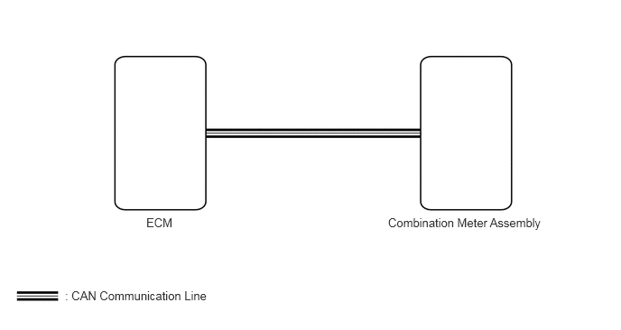
w/ Multi-information Display:
The combination meter assembly receives engine speed signals from the ECM via the CAN communication line. The combination meter assembly displays the engine speed calculated based on the data received from the ECM.
w/o Multi-information Display:
The combination meter assembly controls the tachometer in accordance with engine speed signals from the ECM (except 1HZ) or pickup sensor (for 1HZ).
WIRING DIAGRAM
w/ Multi-information Display:
w/o Multi-information Display:
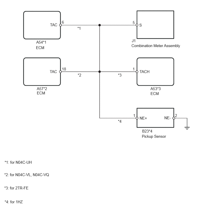
CAUTION / NOTICE / HINT
- NOTICE:
- ·
The meter/gauge system uses the CAN communication system. First, confirm that there is no malfunction in the CAN communication system. Refer to the How to Proceed with Troubleshooting procedure (Click hereVehicle Interior>METER / GAUGE / DISPLAY>METER / GAUGE SYSTEM>HOW TO PROCEED WITH TROUBLESHOOTING).
·When replacing the combination meter assembly, always replace it with a new one. If a combination meter assembly which was installed to another vehicle used, the information stored in it will not match the information from the vehicle and a DTC may be stored.
PROCEDURE
- Result:
Result Proceed to w/ Multi-information Display A w/o Multi-information Display B
A
B
Check for DTCs.
for N04C-UH: Click hereEngine / Hybrid System>N04C-UH (ENGINE CONTROL)>ECD SYSTEM>DTC CHECK / CLEAR
for N04C-VJ: Click hereEngine / Hybrid System>N04C-VJ (ENGINE CONTROL)>ECD SYSTEM>DTC CHECK / CLEAR
for 2TR-FE: Click hereEngine / Hybrid System>2TR-FE (ENGINE CONTROL)>SFI SYSTEM>DTC CHECK / CLEAR
- OK:
ECD system (for N04C-UH, N04C-VJ) or SFI system (for 2TR-FE) DTC is not output.
- Result:
Result Proceed to OK A NG (for N04C-UH) B NG (for N04C-VJ) C NG (for 2TR-FE) D
A
B
Click hereEngine / Hybrid System>N04C-UH (ENGINE CONTROL)>ECD SYSTEM>HOW TO PROCEED WITH TROUBLESHOOTING
C
Click hereEngine / Hybrid System>N04C-VJ (ENGINE CONTROL)>ECD SYSTEM>HOW TO PROCEED WITH TROUBLESHOOTING
D
Click hereEngine / Hybrid System>2TR-FE (ENGINE CONTROL)>SFI SYSTEM>HOW TO PROCEED WITH TROUBLESHOOTING
Using the GTS, perform the Active Test (Click hereVehicle Interior>METER / GAUGE / DISPLAY>METER / GAUGE SYSTEM>DATA LIST / ACTIVE TEST).
| Tester Display | Test Part | Control Range | Diagnostic Note |
|---|---|---|---|
| TachoMeter Operation | Tachometer | OFF, 0, 1000, 2000, 3000, 4000, 5000 or 6000 (rpm) | Make sure that the vehicle is stopped and the engine is idling. |
- OK:
Needle indication is normal according to the GTS operation.
- Result:
Result Proceed to OK A NG (for N04C-UH) B NG (for N04C-VJ) C NG (for 2TR-FE) D
A
B
C
D
Using the GTS, read the Data List (Click hereVehicle Interior>METER / GAUGE / DISPLAY>METER / GAUGE SYSTEM>DATA LIST / ACTIVE TEST).
| Tester Display | Measurement Item/Range | Normal Condition | Diagnostic Note |
|---|---|---|---|
| Engine Rpm | Engine speed / Min.: 0 rpm, Max.: 12750 rpm | Actual engine speed | - |
- OK:
Engine speed displayed on the GTS is almost the same as actual engine speed.
- Result:
Result Proceed to OK A NG (for N04C-UH) B NG (for N04C-VJ) C NG (for 2TR-FE) D
A
B
C
D
Using the GTS, read the Data List (Click hereVehicle Interior>METER / GAUGE / DISPLAY>METER / GAUGE SYSTEM>DATA LIST / ACTIVE TEST).
| Tester Display | Measurement Item/Range | Normal Condition | Diagnostic Note |
|---|---|---|---|
| Engine Speed | Engine speed / Min.: 0 rpm, Max.: 16383 rpm | Actual engine speed | - |
| Tester Display | Measurement Item/Range | Normal Condition | Diagnostic Note |
|---|---|---|---|
| Engine Rpm | Engine speed / Min.: 0 rpm, Max.: 12750 rpm | Actual engine speed | - |
- OK:
"Engine Speed" displayed on GTS is same as "Engine Rpm" displayed on GTS.
- Result:
Result Proceed to OK A NG (for N04C-UH) B NG (for N04C-VJ) C NG (for 2TR-FE) D
A
B
C
D
- Result:
Result Proceed to except 1HZ A for 1HZ B
A
B
Using the GTS, read the Data List (Click hereVehicle Interior>METER / GAUGE / DISPLAY>METER / GAUGE SYSTEM>DATA LIST / ACTIVE TEST).
| Tester Display | Measurement Item/Range | Normal Condition | Diagnostic Note |
|---|---|---|---|
| Engine Rpm | Engine speed / Min.: 0 rpm, Max.: 12750 rpm | Actual engine speed | - |
- OK:
Engine speed displayed on the GTS is almost the same as actual engine speed.
- HINT:
- ·
for N04C-UH: If it is necessary to refer to the ECD system, refer to the following procedures (Click hereEngine / Hybrid System>N04C-UH (ENGINE CONTROL)>ECD SYSTEM>HOW TO PROCEED WITH TROUBLESHOOTING).
·for N04C-VL: If it is necessary to refer to the ECD system, refer to the following procedures (Click hereEngine / Hybrid System>N04C-VL (ENGINE CONTROL)>ECD SYSTEM>HOW TO PROCEED WITH TROUBLESHOOTING).
·for N04C-VQ: If it is necessary to refer to the ECD system, refer to the following procedures (Click hereEngine / Hybrid System>N04C-VQ (ENGINE CONTROL)>ECD SYSTEM>HOW TO PROCEED WITH TROUBLESHOOTING).
·for 2TR-FE: If it is necessary to refer to the SFI system, refer to the following procedures (Click hereEngine / Hybrid System>2TR-FE (ENGINE CONTROL)>SFI SYSTEM>HOW TO PROCEED WITH TROUBLESHOOTING).
- Result:
Result Proceed to OK A NG (except 2TR-FE) B NG (for 2TR-FE) C
A
B
C
Check the input waveform.
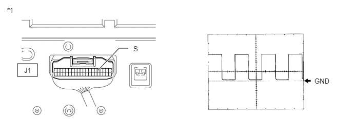
| *1 | Component with harness connected
(Combination Meter Assembly) |
- | - |
Remove the combination meter assembly with the connector still connected.
Connect an oscilloscope to terminal J1-5 (S) and body ground.
Start the engine.
Check the signal waveform according to the condition(s) in the table below.
| Item | Condition |
|---|---|
| Tool Setting | 5 V/DIV., 10 ms/DIV. |
| Vehicle Condition | Engine idling |
- OK:
The waveform is displayed as shown in the illustration.
- HINT:
-
As the vehicle speed increases, the cycle of the signal waveform narrows.
Reinstall the combination meter assembly.
- Result:
Proceed to OK NG
OK
NG
Disconnect the J1 combination meter assembly connector.
Disconnect the B23 pickup sensor connector.
Measure the resistance according to the value(s) in the table below.
- Standard Resistance:
Tester Connection Condition Specified Condition J1-5 (S) - B23-1 (NE+) Always Below 1 Ω B23-2 (NE-) - Body ground Always Below 1 Ω B23-2 (NE-) - Body ground Always 10 kΩ or higher
- Result:
Proceed to OK NG
OK
NG
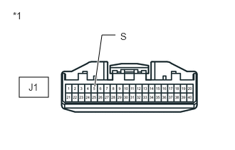
Disconnect the J1 combination meter assembly connector.
Measure the resistance according to the value(s) in the table below.
- Standard Resistance:
Tester Connection Condition Specified Condition J1-5 (S) - Body ground Always Approximately 730 Ω
| *1 | Front view of wire harness connector
(to Combination Meter Assembly) |
- Result:
Proceed to OK NG
OK
NG