N04C-UH FUEL FUEL INJECTOR INSTALLATION
PROCEDURE

 23670
1.INSTALL INJECTOR ASSEMBLY
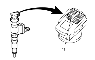
| *1 | Injector Compensation Code |
- NOTICE:
-
Register the injector compensation code of a new fuel injector in the ECM when replacing the fuel injector. Register the injector compensation code in advance so that it can be installed in the correct position.
Install 4 new injection nozzle seats to the cylinder head.
Apply a light amount of clean engine oil to 4 new O-rings.
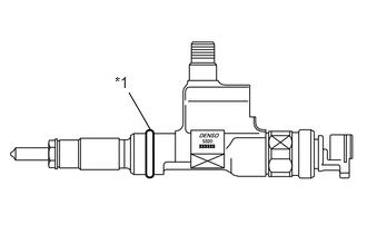
Install an O-ring to each injector as shown in the illustration.
| *1 | O-ring |
Install a new No. 2 cylinder head cover gasket to each injector.
Insert the 4 injectors into the cylinder head.
- NOTICE:
- ·
Check that the insertion part of the fuel injector has no foreign matter attached.
·When reusing a fuel injector, install the same fuel injector that was removed. Otherwise, it could cause the engine to malfunction.
·Carefully insert the fuel injector so that the O-ring is not caught between the cylinder head and the injector.
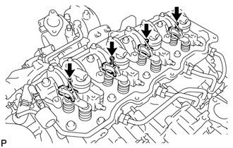
Temporarily install the 4 nozzle holder clamps with the 4 clamp bolts.
- NOTICE:
-
Be sure to install the holder clamps and bolts in their original positions.
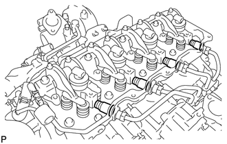
Install the 4 holder seals.
- NOTICE:
-
Securely insert the tip of the holder seal into the fuel injector.
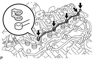
Temporarily install the nozzle leakage pipe assembly through 5 new gaskets by hand with the union bolt and 4 hollow screws.
- NOTICE:
-
Make sure that the hollow screws and nozzle leakage pipe assembly are not deformed or damaged.
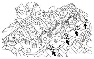
Temporarily tighten the union nuts of injection pipe sub-assemblies No. 1, No. 2, No. 3 and No. 4 by hand.
- NOTICE:
-
If an injector has been replaced, the corresponding injection pipe sub-assembly must also be replaced.
Tighten the 4 nozzle holder clamp bolts.
- Torque:
25 N*m (255 kgf*cm, 18 ft.*lbf)
- NOTICE:
-
After tightening the nozzle holder clamp bolts, check that the fuel injector and the nozzle holder clamp do not interfere with the valve spring.
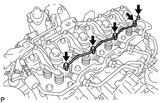
Tighten the 4 hollow screws and union bolt.
- Torque:
13 N*m (130 kgf*cm, 10 ft.*lbf)
- NOTICE:
-
If the nozzle leakage pipe assembly has been tightened to more than the specified torque, replace it with a new one.
Using a union nut wrench (17 mm), tighten the injection pipe union nuts.
- Torque:
35 N*m (357 kgf*cm, 26 ft.*lbf)
- NOTICE:
-
Refer to the torque above when not using the union nut wrench. When using the union nut wrench, calculate the torque in accordance with the lengths of the union nut wrench and torque wrench.
-
Click hereGeneral>INTRODUCTION>REPAIR INSTRUCTION>PRECAUTION
23741B
2.INSTALL INJECTION PIPE CLAMP
Install the 2 injection pipe clamps with the 2 nuts.
Tighten the 2 nuts until the clamp's edges make contact with the engine side clamp's edges.
11201
3.INSTALL CYLINDER HEAD COVER SUB-ASSEMBLY
Install a new cylinder head cover gasket onto the cylinder head cover.
Install the cylinder head cover and the 2 cushions with the 2 bolts.
- Torque:
29 N*m (291 kgf*cm, 21 ft.*lbf)
Install the cylinder head cover cushion rubber.
Install the wire harness and connect the 5 connectors.
11202D
4.INSTALL NO. 2 CYLINDER HEAD COVER SUB-ASSEMBLY
Install the No. 2 cylinder head cover and the 2 stays with the 2 bolts.
- Torque:
29 N*m (291 kgf*cm, 21 ft.*lbf)
12180E
5.INSTALL OIL FILLER CAP SUB-ASSEMBLY
Install the oil filler cap.
25608
6.INSTALL EGR COOLER SUB-ASSEMBLY
17271
7.INSTALL NO. 1 TURBO INSULATOR
17113
8.INSTALL INTAKE PIPE
16206C
9.INSTALL WATER BY-PASS PIPE SUB-ASSEMBLY
10.ADD ENGINE COOLANT
58701A
11.INSTALL FRONT ENGINE SERVICE COVER PANEL SUB-ASSEMBLY
33504F
12.INSTALL SHIFT LEVER SUB-ASSEMBLY
33820B
13.CONNECT TRANSMISSION CONTROL CABLE ASSEMBLY
33531B
14.INSTALL SHIFT AND SELECT LEVER SHAFT DUST BOOT
58534A
15.INSTALL TRANSMISSION COVER MAT
58420
16.INSTALL NO. 2 ENGINE SERVICE HOLE COVER ASSEMBLY
17.BLEED AIR FROM FUEL SYSTEM
18.REGISTRATION INJECTOR COMPENSATION CODE
Register the injector compensation code.
Click hereEngine / Hybrid System>N04C-UH (ENGINE CONTROL)>ECD SYSTEM>REGISTRATION
19.CHECK FOR INJECTOR COMPENSATION CODE
20.INSPECT FOR FUEL LEAK
21.INSPECT FOR COOLANT LEAK
22.INSPECT FOR OIL LEAK
58521D
23.INSTALL ENGINE SERVICE HOLE COVER MAT
58734B
24.INSTALL ENGINE SERVICE COVER REAR WEATHERSTRIP
58410
25.INSTALL ENGINE SERVICE HOLE COVER