2GR-FE FUEL FUEL INJECTOR INSTALLATION
PROCEDURE

 23250
1.INSTALL FUEL INJECTOR ASSEMBLY
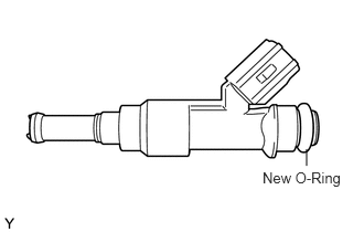
Apply a light coat of spindle oil or gasoline to new O-rings, and install them to each injector.
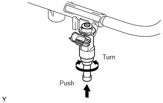
Apply a light coat of spindle oil or gasoline where the fuel delivery pipe contacts the O-ring.
Push the fuel injector while turning it to install the injector in the fuel delivery pipe.
Position the fuel injector connector outward.
- NOTICE:
- ·
Be careful not to twist the O-ring.
·After installing the fuel injector, check that it turns smoothly. If not, reinstall it with a new O-ring.
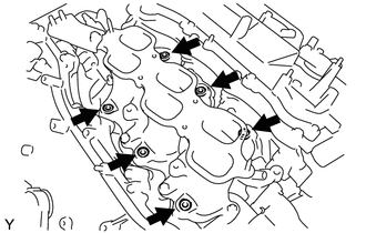
Install 6 new injector vibration insulators to the intake manifold.
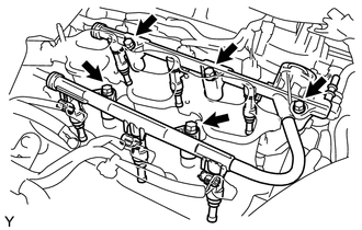
Place the fuel delivery pipe with the 6 fuel injectors installed in position on the intake manifold.
- NOTICE:
-
Be careful not to drop the fuel injectors when installing the fuel delivery pipe.
Temporarily install the 5 bolts which are used to hold the fuel delivery pipe to the intake manifold.
- NOTICE:
-
After installing the fuel injectors, check that they turn smoothly. If not, reinstall the injectors with new O-rings.
Tighten the 5 bolts which are used to hold the fuel delivery pipe to the intake manifold.
- Torque:
- 21 N*m (214 kgf*cm, 15 ft.*lbf)
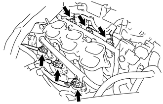
Connect the 6 fuel injector connectors.
23901
2.CONNECT FUEL TUBE SUB-ASSEMBLY
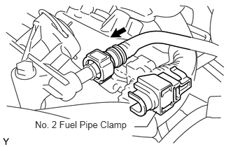
Push in the tube connector onto the pipe until the tube connector makes a "click" sound.
- NOTICE:
- ·
Before connecting the tube, make sure that it is not damaged. Make sure that there is no dirt present on the connecting surfaces.
·After connecting, check that the fuel tube connector and the pipe are securely connected by pulling on them.
Install the No. 2 fuel pipe clamp.
17190
3.INSTALL INTAKE AIR SURGE TANK ASSEMBLY
- NOTICE:
-
DO NOT apply oil to the bolts listed below:
Tightening Parts Surge Tank and Intake Manifold No. 1 Surge Tank Stay and Surge Tank Throttle Body Bracket and Surge Tank
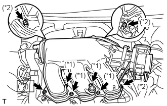
Install a new gasket to the intake air surge tank.
Using a 5 mm hexagon socket wrench, install the 4 bolts. (*1)
- Torque:
- 18 N*m (184 kgf*cm, 13 ft.*lbf)
Install the intake air surge tank with the 2 nuts and 2 bolts. (*2)
- Torque:
- Nut : 16 N*m (163 kgf*cm, 12 ft.*lbf)
- Bolt : 21 N*m (214 kgf*cm, 15 ft.*lbf)
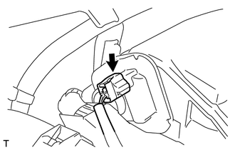
Connect the connector.
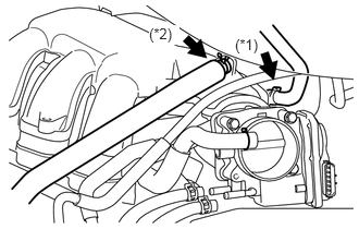
Connect the union to check valve hose. (*1)
Connect the No. 1 ventilation hose. (*2)
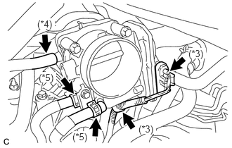
Connect the throttle with motor body assembly connector and clamp. (*3)
Connect the vapor feed hose. (*4)
Connect the 2 water by-pass hoses to the throttle with motor body assembly. (*5)
17705
4.INSTALL AIR CLEANER CAP
5.ADD ENGINE COOLANT
6.CONNECT CABLE TO NEGATIVE BATTERY TERMINAL
7.INSPECT FOR ENGINE COOLANT LEAK
51442
8.INSTALL NO. 2 ENGINE UNDER COVER
9.INSPECT FOR FUEL LEAK
11209
10.INSTALL V-BANK COVER SUB-ASSEMBLY
55712
11.INSTALL FRONT COWL TOP OUTSIDE PANEL WITH WINDSHIELD WIPER MOTOR AND LINK
47202
12.INSTALL BRAKE MASTER CYLINDER RESERVOIR BRACKET
55781F
13.INSTALL COWL TOP VENTILATOR LOUVER
53866J
14.INSTALL FRONT FENDER TO COWL SIDE SEAL RH
53867H
15.INSTALL FRONT FENDER TO COWL SIDE SEAL LH
85291A
16.INSTALL FRONT WIPER ARM AND BLADE ASSEMBLY RH
85291B
17.INSTALL FRONT WIPER ARM AND BLADE ASSEMBLY LH
18.INSTALL FRONT WIPER ARM HEAD CAP