Home › Engine / Hybrid System › 2AZ-FE ENGINE MECHANICAL › ENGINE UNIT › from 2016.05
RM24M0E _51 Engine / Hybrid System _059548 2AZ-FE ENGINE MECHANICAL _0291836 ENGINE UNIT A

2AZ-FE ENGINE MECHANICAL  ENGINE UNIT  REPLACEMENT  


CAUTION / NOTICE / HINT

PROCEDURE

Hide 11301C 1.REPLACE TIMING CHAIN COVER OIL SEAL

HINT:

There are 2 methods to replace the oil seal.


a.

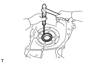
If the timing chain cover is removed from the cylinder block:
i.
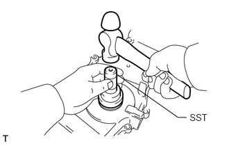
A112248

Using a screwdriver and hammer, tap out the oil seal.


ii.

Apply multi-purpose grease to the lip of a new oil seal.

NOTICE:

Keep the lip free of foreign objects.


iii.
A112249E02
2.847,1.675 3.191,1.841 0.343,0.166 10 SST 1.756,1.116 2.671,1.759 2.671,1.759 2.8,1.759 false

Using SST and a hammer, tap in the new oil seal until its surface is flush with the timing chain cover edge.

SST
09223-22010  

NOTICE:

Do not tap the oil seal at an angle.


b.

If the timing chain cover oil seal is installed to the cylinder block:

i.

Remove the fan and generator V belt (See page Engine / Hybrid System>2AZ-FE ENGINE MECHANICAL>DRIVE BELT>REMOVAL).


ii.

iii.
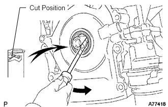
A077418E03
0.24,1.156 0.406,0.156 0.406,0.156 0.531,0.156 false 0.604,0.073 1.385,0.417 0.781,0.344 10 true Cut Position

Using a knife, cut off the lip of the oil seal.


iv.

Using a screwdriver with its tip wrapped with tape, pry out the oil seal.

NOTICE:

After removing, check the crankshaft for damage. If damaged, smooth the surface with 400-grit sandpaper.


v.

Apply multi-purpose grease to the lip of a new oil seal.

NOTICE:

Keep the lip free of foreign objects.


vi.
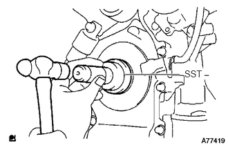
A077419E03
1.885,1.125 2.708,1.125 true 2.781,1.031 3.083,1.292 0.302,0.26 10 true SST

Using SST and a hammer, tap in the new oil seal until its surface is flush with the timing chain cover edge.

SST
09223-22010  

NOTICE:

Do not tap the oil seal at an angle.


vii.

viii.

Install the fan and generator V belt (See page Engine / Hybrid System>2AZ-FE ENGINE MECHANICAL>DRIVE BELT>INSTALLATION).


Hide 11401L 2.REPLACE REAR CRANKSHAFT OIL SEAL
a.
A098356E02
0.49,1.688 0.49,0.99 false 0.115,1.698 0.906,1.854 0.792,0.156 10 false Cut Position

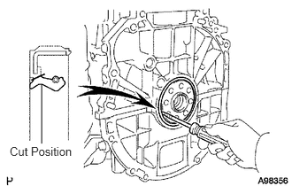
Using a knife, cut off the lip of the oil seal.


b.

Using a screwdriver with its tip wrapped with tape, pry out the oil seal.

NOTICE:

After removing, check the crankshaft for damage. If damaged, smooth the surface with 400-grit sandpaper.


c.

Apply multi-purpose grease to the lip of a new oil seal.

NOTICE:

Keep the lip free of foreign objects.


d.
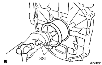
A077422E02
1.344,1.458 1.479,1.854 1.479,1.854 1.823,1.552 false 1.323,1.885 1.646,2.052 0.323,0.167 10 false SST

Using SST and a hammer, tap in the new oil seal until its surface is flush with the rear oil seal retainer edge.

SST
09223-15030  
09950-70010  (09951-07100)

NOTICE:
·

Wipe any extra grease off of the crankshaft.

·

Do not tap the oil seal at an angle.


Hide 3.REPLACE STUD BOLT

NOTICE:

If the stud bolt is deformed or the threads are damaged, replace it.


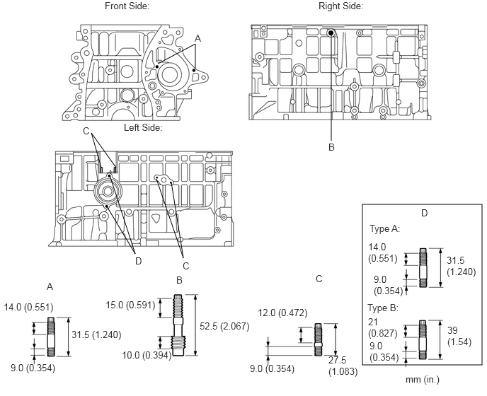
a.

Remove the 8 stud bolts.


b.

Install the 8 stud bolts into the cylinder block.
A384340E04
5.333,3.01 7.094,5.375 1.76,2.365 4.875,0.49 4.875,2.073 false 2.875,1.01 2.875,0.646 2.875,0.646 2.323,0.938 false 1.615,2.583 1.99,3.74 1.99,3.74 1.573,3.042 false 1.708,2.469 1.344,1.958 1.344,1.958 1.49,2.469 false 2.521,2.688 2.698,3.802 2.698,3.802 2.302,2.635 false 1.542,0 2.271,0.188 0.729,0.188 10 false Front Side: 4.688,0 5.427,0.167 0.74,0.167 10 false Right Side: 1.823,1.792 2.469,1.979 0.646,0.188 10 false Left Side: 0.052,4.438 0.958,4.792 0.906,0.354 10 false 14.0 (0.551) 0.156,5.333 0.854,5.521 0.698,0.188 10 false 9.0 (0.354) 1.552,4.406 2.323,4.604 0.771,0.198 10 false 15.0 (0.591) 1.792,5.146 2.583,5.344 0.792,0.198 10 false 10.0 (0.394) 2.938,4.719 3.708,4.927 0.771,0.208 10 false 52.5 (2.067) 3.792,4.521 4.583,4.729 0.792,0.208 10 false 12.0 (0.472) 4.833,5.219 5.302,5.594 0.469,0.375 10 false 27.5 (1.083) 2.865,0.479 3.021,0.615 0.156,0.135 10 false A 4.833,2.083 4.969,2.281 0.135,0.198 10 false B 2.688,3.833 2.813,3.979 0.125,0.146 10 false C 1.99,3.76 2.146,3.948 0.156,0.188 10 false D 3.677,5.344 4.375,5.531 0.698,0.188 10 false 9.0 (0.354) 1.052,4.844 1.823,5.031 0.771,0.188 10 false 31.5 (1.240) 0.688,4.135 0.844,4.323 0.156,0.188 10 false A 4.646,4.021 4.771,4.167 0.125,0.146 10 false C 2.594,4.042 2.729,4.24 0.135,0.198 10 false B 1.219,1.844 1.344,1.99 0.125,0.146 10 false C 5.969,5.5 6.521,5.719 0.552,0.219 10 false mm (in.) 6.198,3.052 6.354,3.24 0.156,0.188 10 false D 5.417,3.552 6.031,3.906 0.615,0.354 10 false 14.0 (0.551) 5.5,4.031 5.979,4.365 0.479,0.333 10 false 9.0 (0.354) 5.438,3.281 6.083,3.469 0.646,0.188 10 false Type A: 5.406,4.448 6.052,4.635 0.646,0.188 10 false Type B: 6.573,3.75 7.115,4.156 0.542,0.406 10 false 31.5 (1.240) 5.417,4.656 5.969,5.01 0.552,0.354 10 false 21 (0.827) 5.438,5.01 5.917,5.344 0.479,0.333 10 false 9.0 (0.354) 6.583,4.781 7.01,5.188 0.427,0.406 10 false 39 (1.54)

Torque:
Stud Bolt A, C, D : 5.0 N*m (51 kgf*cm, 44 in.*lbf)
Stud Bolt B : 9.5 N*m (97 kgf*cm, 84 in.*lbf)


Hide 4.REPLACE RING PIN

NOTICE:

It is not necessary to remove a ring pin unless it is being replaced.


a.

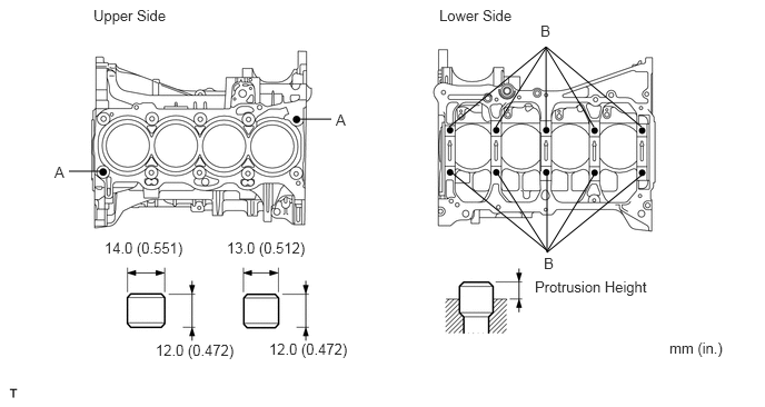
Remove the 12 ring pins.


b.

Using a plastic-faced hammer, install 12 new ring pins.
A112251E07
0.646,1.604 0.938,1.604 false 2.813,1.115 3.104,1.115 false 4.208,1.188 5.115,0.438 5.115,0.438 6.01,1.188 false 5.115,1.188 5.115,0.448 false 4.646,1.188 5.115,0.448 false 5.563,1.188 5.115,0.448 false 6.042,1.615 5.135,2.354 5.135,2.354 4.229,1.615 false 5.125,1.625 5.125,2.365 false 4.667,1.635 5.135,2.365 false 5.573,1.625 5.125,2.354 false 0.875,0.063 1.667,0.26 0.792,0.198 10 false Upper Side 4.115,0.063 4.938,0.281 0.823,0.219 10 false Lower Side 3.146,1.042 3.365,1.25 0.219,0.208 10 false A 5.063,0.208 5.281,0.417 0.219,0.208 10 false B 5.094,2.385 5.313,2.594 0.219,0.208 10 false B 0.51,1.531 0.729,1.74 0.219,0.208 10 false A 0.979,2.24 1.823,2.448 0.844,0.208 10 false 14.0 (0.551) 2.125,2.24 2.969,2.448 0.844,0.208 10 false 13.0 (0.512) 1.458,3.198 2.302,3.406 0.844,0.208 10 false 12.0 (0.472) 2.521,3.188 3.365,3.396 0.844,0.208 10 false 12.0 (0.472) 5.01,2.604 6.292,2.802 1.281,0.198 10 false Protrusion Height 6.271,3.177 6.833,3.375 0.563,0.198 10 false mm (in.)

Standard protrusion height:
Item Specified Condition
A 6.0 mm (0.236 in.)
B 5.0 mm (0.197 in.)


Hide 5.REPLACE STRAIGHT PIN

NOTICE:

It is not necessary to remove a straight pin unless it is being replaced.


a.

Remove the 8 straight pins.


b.

Using a plastic-faced hammer, install 8 new straight pins.
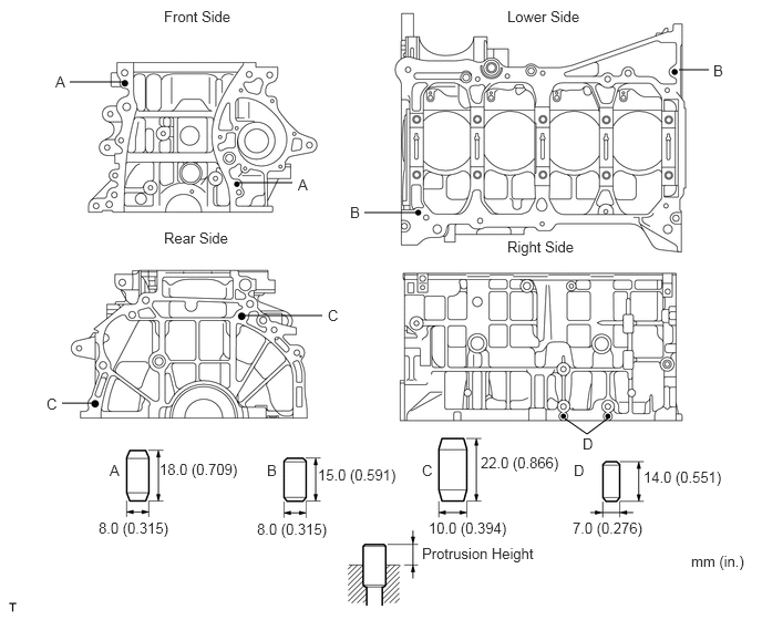
A112252E14
0.656,0.771 1.156,0.771 false 2.25,1.719 2.75,1.719 false 3.427,2 3.927,2 false 2.302,2.969 3.031,2.969 false 5.313,3.938 5.521,4.083 5.521,4.083 5.729,3.927 false 6.385,0.656 6.667,0.656 false 0.583,3.792 0.865,3.792 false 0.521,0.688 0.698,0.885 0.177,0.198 10 false A 2.802,1.656 2.979,1.854 0.177,0.198 10 false A 1.031,4.344 1.208,4.542 0.177,0.198 10 false A 3.083,2.885 3.26,3.083 0.177,0.198 10 false C 3.969,4.344 4.146,4.542 0.177,0.198 10 false C 5.479,4.094 5.656,4.292 0.177,0.198 10 false D 5.396,4.344 5.573,4.542 0.177,0.198 10 false D 0.438,3.719 0.615,3.917 0.177,0.198 10 false C 2.51,4.344 2.688,4.542 0.177,0.198 10 false B 3.292,1.917 3.469,2.115 0.177,0.198 10 false B 6.708,0.583 6.885,0.781 0.177,0.198 10 false B 1.5,4.333 2.292,4.552 0.792,0.219 10 false 18.0 (0.709) 0.927,4.885 1.719,5.104 0.792,0.219 10 false 8.0 (0.315) 2.417,4.896 3.208,5.115 0.792,0.219 10 false 8.0 (0.315) 4.031,4.885 4.823,5.104 0.792,0.219 10 false 10.0 (0.394) 5.385,4.885 6.177,5.104 0.792,0.219 10 false 7.0 (0.276) 2.99,4.385 3.781,4.604 0.792,0.219 10 false 15.0 (0.591) 4.521,4.271 5.313,4.49 0.792,0.219 10 false 22.0 (0.866) 6.052,4.406 6.844,4.625 0.792,0.219 10 false 14.0 (0.551) 3.969,5.125 5.115,5.302 1.146,0.177 10 false Protrusion Height 6.5,5.198 7.042,5.406 0.542,0.208 10 false mm (in.) 1.542,0.073 2.448,0.26 0.906,0.188 10 false Front Side 1.542,2.156 2.448,2.344 0.906,0.188 10 false Rear Side 4.771,2.24 5.677,2.427 0.906,0.188 10 false Right Side 4.771,0.073 5.677,0.26 0.906,0.188 10 false Lower Side

Standard protrusion height:
Item Specified Condition
A 8.0 mm (0.315 in.)
B 7.5 mm (0.295 in.)
C 12.0 mm (0.472 in.)
D 5.0 mm (0.197 in.)