2AZ-FE ENGINE MECHANICAL TIMING CHAIN REMOVAL
CAUTION / NOTICE / HINT
PROCEDURE

 1.DISCONNECT CABLE FROM NEGATIVE BATTERY TERMINAL
- NOTICE:
-
When disconnecting the cable, some systems need to be initialized after the cable is reconnected (See page General>INTRODUCTION>REPAIR INSTRUCTION>INITIALIZATION).
53292A
2.REMOVE UPPER RADIATOR SUPPORT SEAL
3.REMOVE FRONT WHEEL RH
51441
4.REMOVE NO. 1 ENGINE UNDER COVER
53701
5.REMOVE FRONT FENDER APRON RH
6.DRAIN ENGINE OIL
17410
7.REMOVE FRONT EXHAUST PIPE
51217A
8.REMOVE FRONT SUSPENSION MEMBER REINFORCEMENT RH
9.REMOVE COWL TOP OUTER PANEL WITH WINDSHIELD WIPER MOTOR AND LINK
Remove the cowl top outer panel with windshield wiper motor and link (See page Vehicle Interior>WIPER / WASHER>FRONT WIPER MOTOR>REMOVAL).
16361A
10.REMOVE FAN AND GENERATOR V BELT
27020
11.REMOVE GENERATOR ASSEMBLY
16470
12.REMOVE RADIATOR RESERVOIR ASSEMBLY
16611
13.REMOVE RADIATOR RESERVOIR BRACKET
12305
14.REMOVE ENGINE MOUNTING INSULATOR RH
12361A
15.REMOVE FRONT ENGINE MOUNTING INSULATOR
16603B
16.REMOVE IDLER PULLEY BRACKET
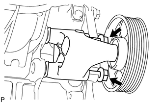
Loosen the 2 bolts and remove the idler pulley bracket with the 2 bolts.
19500
17.REMOVE IGNITION COIL ASSEMBLY
11201
18.REMOVE CYLINDER HEAD COVER SUB-ASSEMBLY
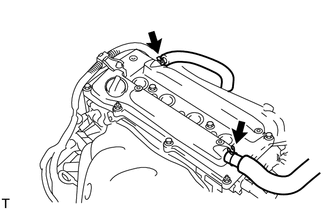
Disconnect the 2 ventilation hoses from the cylinder head cover.
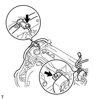
Remove the 2 bolts and disconnect the 2 engine wires.
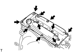
Remove the 8 bolts, 2 nuts and cylinder head cover.
19.SUSPEND ENGINE ASSEMBLY
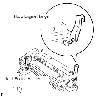
Install the No. 1 and No. 2 engine hangers with the bolts.
- Torque:
- 38 N*m (387 kgf*cm, 28 ft.*lbf)
| Item | Part No. |
|---|---|
| No. 1 engine hanger | 12281-28010 or
12281-0H010 |
| No. 2 engine hanger | 12282-28010 or
12282-0H010 |
| Bolt | 91552-81020 or
90105-C0076 |
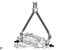
Attach a sling device to the engine hangers and chain block.
12101
20.REMOVE OIL PAN SUB-ASSEMBLY
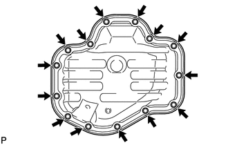
Remove the 12 bolts and 2 nuts.
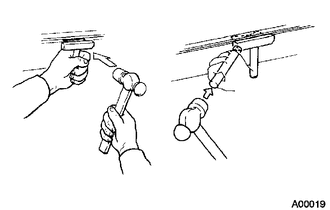
Insert the blade of an oil pan seal cutter between the crankcase, chain cover and oil pan, then cut off the applied sealer and remove the oil pan.
- NOTICE:
-
Be careful not to damage the contact surfaces of the crankcase, chain cover and oil pan.
21.SET NO. 1 CYLINDER TO TDC/COMPRESSION
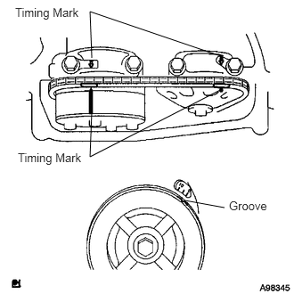
Turn the crankshaft pulley until its groove and the timing mark "0" of the timing chain cover are aligned.
Check that each timing mark of the camshaft timing gear and sprocket is aligned with each timing mark located on the No. 1 and No. 2 bearing caps as shown in the illustration.
If not, turn the crankshaft by 1 revolution (360°) to align the timing marks as above.
13471
22.REMOVE CRANKSHAFT PULLEY
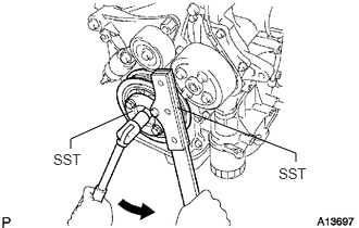
Using SST, secure the pulley in place and loosen the pulley bolt.
- SST
- 09213-54015 (91651-60855)
09330-00021
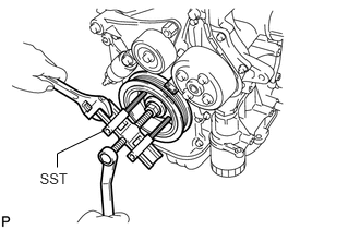
Using SST, remove the crankshaft pulley.
- SST
- 09950-50013 (09951-05010, 09952-05010, 09953-05020, 09954-05021)
09950-40011 (09957-04010)
13540
23.REMOVE NO. 1 CHAIN TENSIONER ASSEMBLY
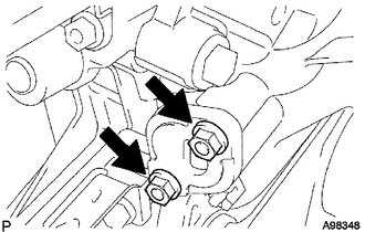
Remove the 2 nuts, chain tensioner and gasket.
- NOTICE:
-
Do not turn the crankshaft without the chain tensioner.
12315A
24.REMOVE ENGINE MOUNTING BRACKET RH
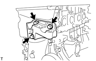
Remove the 3 bolts and engine mounting bracket RH.
16620
25.REMOVE V-RIBBED BELT TENSIONER ASSEMBLY
Lift the engine upward using a transmission jack.
- NOTICE:
-
Do not lift the engine more than necessary.
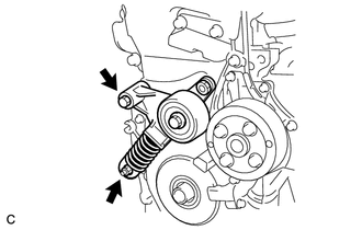
Remove the bolt, nut and V-ribbed belt tensioner.
11301K
26.REMOVE CRANKSHAFT POSITION SENSOR
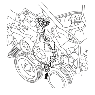
Disconnect the connector from the connector bracket.
Disconnect the 2 wire harness clamps.
Remove the bolt and crank position sensor.
11302
27.REMOVE TIMING CHAIN COVER SUB-ASSEMBLY
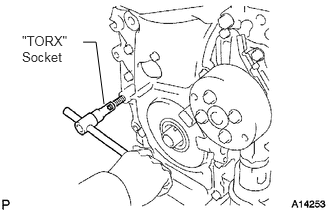
Using an E10 "TORX" socket, remove the stud bolt for the V-ribbed belt tensioner.
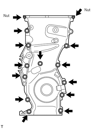
Remove the 12 bolts and 2 nuts.
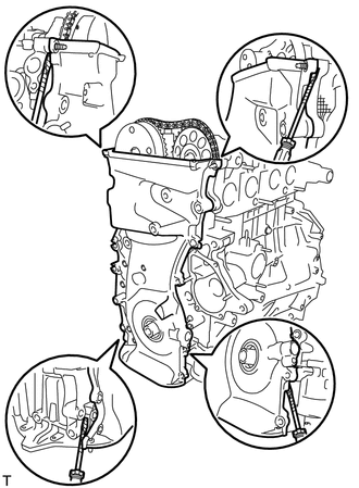
Remove the timing chain cover by prying the portions between the timing chain cover, cylinder head and cylinder block with a screwdriver.
- NOTICE:
-
Be careful not to damage the contact surfaces of the timing chain cover, cylinder head and cylinder block.
19315
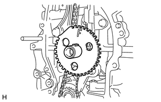
28.REMOVE NO. 1 CRANKSHAFT POSITION SENSOR PLATE
13566B
29.REMOVE TIMING CHAIN GUIDE
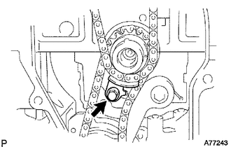
Remove the bolt and timing chain guide.
13559
30.REMOVE CHAIN TENSIONER SLIPPER
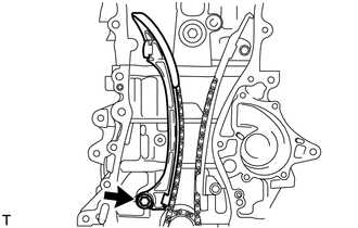
Remove the bolt and chain tensioner slipper.
13561
31.REMOVE NO. 1 CHAIN VIBRATION DAMPER
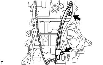
Remove the 2 bolts and chain vibration damper.
13506
32.REMOVE CHAIN SUB-ASSEMBLY
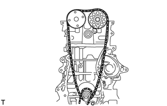
13521
33.REMOVE CRANKSHAFT TIMING SPROCKET
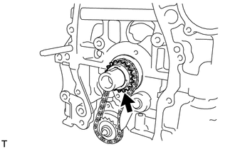
13507
34.REMOVE NO. 2 CHAIN SUB-ASSEMBLY
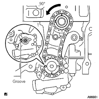
Turn the crankshaft by 90° counterclockwise to align the adjusting hole of the oil pump drive shaft sprocket with the groove of the oil pump.
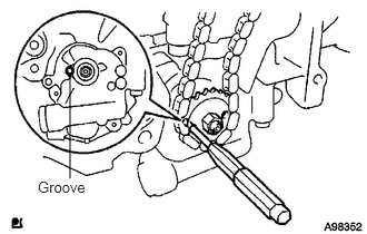
Insert a 4 mm diameter bar into the adjusting hole of the oil pump drive shaft sprocket to lock the gear in position, and then remove the nut.
Remove the bolt, chain tensioner plate and spring.
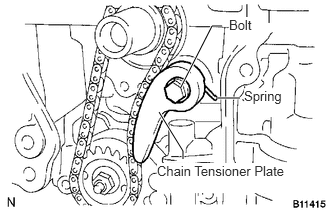
Remove the oil pump drive sprocket, oil pump drive shaft sprocket and No. 2 chain.