2AZ-FE COOLING WATER PUMP INSTALLATION
CAUTION / NOTICE / HINT
- HINT:
-
Check whether the engine is TMC made or not by referring to the following illustration.
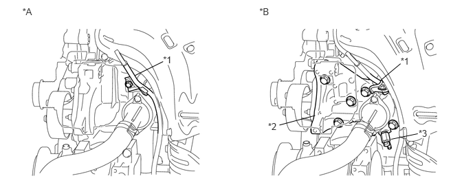 3.93,0.096 4.173,0.285 0.243,0.189 10 *B 0.339,0.096 0.588,0.285 0.249,0.189 10 *A 2.471,0.822 2.640,0.977 0.169,0.154 10 *1 2.471,0.932 2.045,1.143 false 6.069,0.84 6.239,0.994 0.169,0.154 10 *1 6.069,0.964 5.767,1.216 false 4.061,1.835 4.230,1.989 0.169,0.154 10 *2 6.342,1.937 6.511,2.092 0.169,0.154 10 *3 4.233,1.894 4.774,1.749 false 6.33,2.025 5.924,2.109 false
Text in Illustration *A for TMC Made Engine *B except TMC Made Engine *1 Engine Oil Level Dipstick Guide *2 Water Inlet Housing *3 Water Inlet Housing Drain Cock Assembly - -
PROCEDURE

 16100
1.INSTALL WATER PUMP ASSEMBLY (for TMC Made Engine)
Remove any old seal packing material from the contact surfaces.
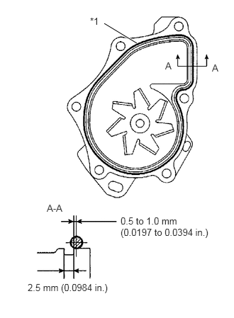
Apply a continuous line of seal packing as shown in the illustration.
| *1 | Seal Packing |
- Seal packing:
Toyota Genuine Seal Packing 1282B, Three Bond 1282B or equivalent
- Standard seal diameter:
2.2 to 2.5 mm (0.0866 to 0.0984 in.)
- NOTICE:
- ·
Remove any oil from the contact surfaces.
·The parts must be set within 3 minutes of applying seal packing. Otherwise, the material must be removed and reapplied.
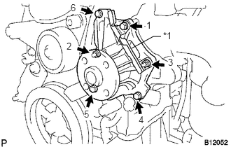
Temporarily install the water pump and clamp bracket with the 4 bolts and 2 nuts.
| *1 | Clamp Bracket |
Tighten the 4 bolts and 2 nuts in the order shown in the illustration.
- Torque:
- 9.0 N*m (92 kgf*cm, 80 in.*lbf)
Install the wire of the crankshaft position sensor onto the clamp bracket.
Install the clamp of the crankshaft position sensor onto the water pump.
16100
2.INSTALL WATER PUMP ASSEMBLY (except TMC Made Engine)
Remove any old seal packing material from the contact surfaces.
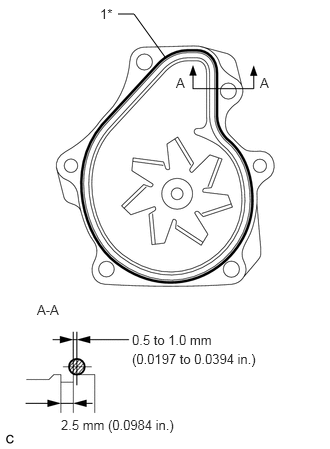
Apply a continuous line of seal packing as shown in the illustration.
| *1 | Seal Packing |
- Seal packing:
Toyota Genuine Seal Packing 1282B, Three Bond 1282B or equivalent
- Standard seal diameter:
2.2 to 2.5 mm (0.0866 to 0.0984 in.)
- NOTICE:
- ·
Remove any oil from the contact surfaces.
·The parts must be set within 3 minutes of applying seal packing. Otherwise, the material must be removed and reapplied.
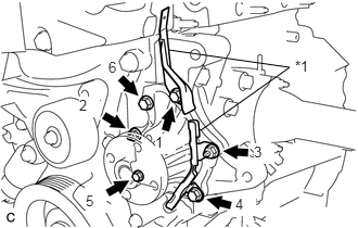
Temporarily install the water pump assembly and 2 clamp brackets with the 4 bolts and 2 nuts.
| *1 | Clamp Bracket |
Tighten the 4 bolts and 2 nuts in the order shown in the illustration.
- Torque:
- 9.0 N*m (92 kgf*cm, 80 in.*lbf)
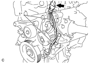
Install the wire of the crankshaft position sensor onto the clamp brackets.
| *1 | Clamp Bracket |
Connect the connector of the crankshaft position sensor.
16173
3.INSTALL WATER PUMP PULLEY
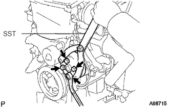
Using SST, install the water pump pulley with the 4 bolts.
- SST
- 09960-10010 (09962-01000, 09963-00700)
- Torque:
- 26 N*m (265 kgf*cm, 19 ft.*lbf)
27020
4.INSTALL GENERATOR ASSEMBLY
16361A
5.INSTALL FAN AND GENERATOR V BELT
51217A
6.INSTALL FRONT SUSPENSION MEMBER REINFORCEMENT RH
7.CONNECT CABLE TO NEGATIVE BATTERY TERMINAL
8.ADD ENGINE COOLANT
9.INSPECT FOR COOLANT LEAK
53292A
10.INSTALL UPPER RADIATOR SUPPORT SEAL
53701
11.INSTALL FRONT FENDER APRON RH
51441
12.INSTALL NO. 1 ENGINE UNDER COVER
13.PERFORM INITIALIZATION
Perform initialization (See page General>INTRODUCTION>REPAIR INSTRUCTION>INITIALIZATION).
- NOTICE:
-
Certain systems need to be initialized after disconnecting and reconnecting the cable from the negative (-) battery terminal.