STEERING COLUMN STEERING COLUMN ASSEMBLY INSTALLATION
CAUTION / NOTICE / HINT
- HINT:
-
A bolt without a torque specification is shown in the standard bolt chart (See page General>SPECIFICATIONS>STANDARD BOLT>SPECIFIED TORQUE FOR STANDARD BOLTS).
PROCEDURE

 45250
1.INSTALL STEERING COLUMN ASSEMBLY
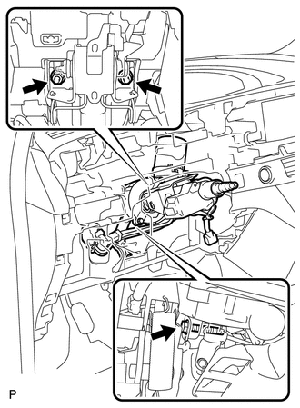
Install the steering column with the bolt and 2 nuts.
- Torque:
- Bolt : 36 N*m (370 kgf*cm, 26 ft.*lbf)
- Nut : 25 N*m (255 kgf*cm, 18 ft.*lbf)
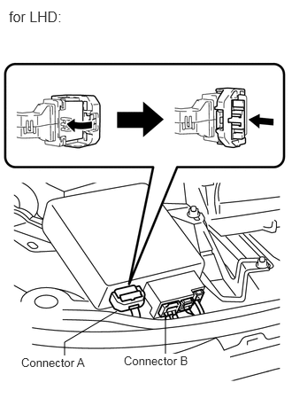
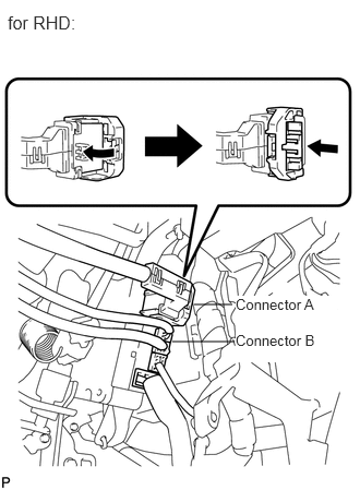
Connect connector A and B to the power steering ECU.
Connect the connectors and clamp the wire harnesses onto the steering column bracket.
55302A
2.INSTALL UPPER INSTRUMENT PANEL SUB-ASSEMBLY (for LHD)
Install the upper instrument panel (see page Vehicle Interior>INTERIOR PANEL>UPPER INSTRUMENT PANEL>INSTALLATION).
45260
3.INSTALL NO. 2 STEERING INTERMEDIATE SHAFT ASSEMBLY
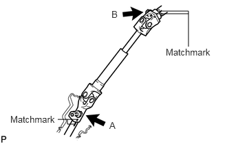
Align the matchmarks on the steering intermediate shaft and steering sliding yoke, and temporarily install them with bolt B.
- Torque:
- 35 N*m (360 kgf*cm, 26 ft.*lbf)
Align the matchmarks on the steering sliding yoke and steering gear, and install them with bolt A.
- Torque:
- 35 N*m (360 kgf*cm, 26 ft.*lbf)
45259A
4.INSTALL COLUMN HOLE COVER SILENCER SHEET
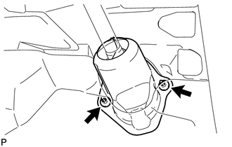
Install the column hole cover plate with the 2 clips.
Install the floor carpet.
55432B
5.INSTALL LOWER INSTRUMENT PANEL FINISH PANEL
with knee airbag :
Install the lower instrument panel finish panel (see page Vehicle Interior>INTERIOR PANEL>LOWER INSTRUMENT PANEL>INSTALLATION).
without knee airbag :
Install the lower instrument panel finish panel (see page Vehicle Interior>INTERIOR PANEL>LOWER INSTRUMENT PANEL>INSTALLATION).
6.INSTALL TURN SIGNAL SWITCH ASSEMBLY WITH SPIRAL CABLE
Attach the clamp to install the turn signal switch with spiral cable onto the steering column.
Install the connectors to the turn signal switch with spiral cable.
45286
7.INSTALL STEERING COLUMN COVER
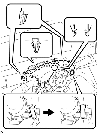
Engage the 3 claws, 4 clips, and 2 pins to install the upper steering column cover.
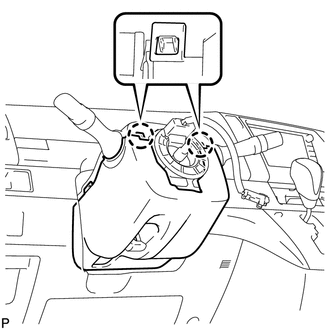
Engage the 2 claws to install the lower steering column cover.
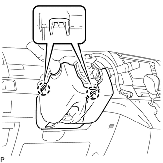
Engage the 2 claws.
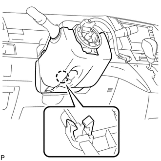
Engage the claw.
- HINT:
-
Press the area around the claw to engage it.
45100
8.INSTALL STEERING WHEEL ASSEMBLY
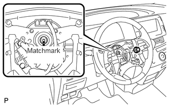
Align the matchmarks and install the steering wheel onto the steering column.
Install the nut.
- Torque:
- 50 N*m (510 kgf*cm, 37 ft.*lbf)
45130
9.INSTALL STEERING PAD ASSEMBLY
10.POSITION FRONT WHEELS FACING STRAIGHT AHEAD
28800
11.CONNECT CABLE TO NEGATIVE BATTERY TERMINAL
12.INSPECT SRS WARNING LIGHT
Inspect the SRS warning light (see page Vehicle Interior>SUPPLEMENTAL RESTRAINT SYSTEMS>AIRBAG SYSTEM>DIAGNOSIS SYSTEM).
13. PERFORM INITIALIZATION
Perform initialization (see page General>INTRODUCTION>REPAIR INSTRUCTION>INITIALIZATION).
- NOTICE:
-
Certain systems need to be initialized after disconnecting and reconnecting the cable from the negative (-) battery terminal.