ENGINE HOOD / DOOR FRONT DOOR REASSEMBLY
CAUTION / NOTICE / HINT
- HINT:
- ·
Use the same procedures for the RH side and LH side.
·The procedures listed below are for the LH side.
·A bolt without a torque specification is shown in the standard bolt chart (See page General>SPECIFICATIONS>STANDARD BOLT>SPECIFIED TORQUE FOR STANDARD BOLTS).
PROCEDURE

 1.INSTALL FRONT DOOR MUDGUARD SUB-ASSEMBLY (for Standard)
2.INSTALL FRONT DOOR MUDGUARD SUB-ASSEMBLY (for Sport Package)
67663D
3.INSTALL DOOR FRAME GARNISH LH
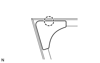
Attach the claw to install the garnish.
82152
4.INSTALL FRONT DOOR WIRE LH
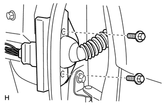
Install the wire with the 2 bolts.
- Torque:
- Reference : 8.0 N*m (82 kgf*cm, 71 in.*lbf)
- NOTICE:
-
In order to prevent water leakage, be sure that the lip of the rubber grommet does not turn up or is not deformed when installing the wire.
Connect the wire clips.
67862
5.INSTALL FRONT DOOR WEATHERSTRIP LH
Attach the clips to install the weatherstrip.
68620
6.INSTALL FRONT DOOR CHECK ASSEMBLY LH
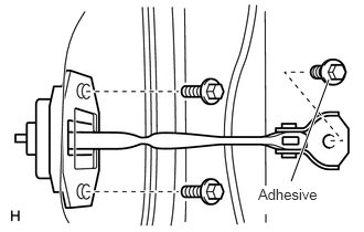
Apply MP grease to the sliding area of the door check.
Install the door check to the door panel with the 2 bolts.
- Torque:
- 8.0 N*m (82 kgf*cm, 71 in.*lbf)
- HINT:
-
Install the door check so that the rivet head is up.
Apply adhesive to the threads of the bolt.
- Adhesive:
Toyota Genuine Adhesive 1324, Three Bond 1344 or equivalent
Install the door check to the body with the bolt.
- Torque:
- 29 N*m (296 kgf*cm, 21 ft.*lbf)
69202A
7.INSTALL FRONT DOOR OUTSIDE HANDLE FRAME SUB-ASSEMBLY LH
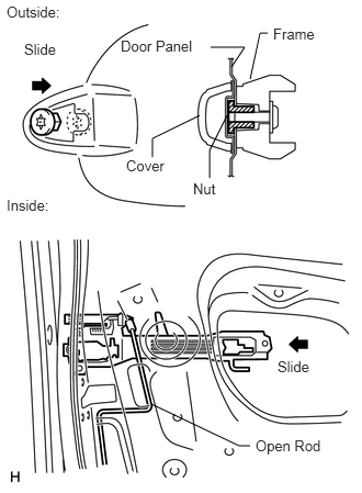
Install the open rod to the outside handle frame.
Slide the outside handle frame in the direction indicated by the arrow in the illustration.
Using a T30 "TORX" socket, install the outside handle frame with the screw.
- Torque:
- 7.0 N*m (71 kgf*cm, 62 in.*lbf)
- NOTICE:
-
Insert a cover between the nut and the door panel.
Install the outside handle pads front and rear.
w/ Entry Function:
Connect the connector.
69220
8.INSTALL FRONT DOOR HANDLE ASSEMBLY OUTSIDE LH
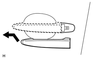
Install the outside handle by pushing in the direction indicated by the arrow in the illustration.
- NOTICE:
-
If the release plate is not pulled and held when installing the outside handle, it will strike against the outside handle and become damaged.
w/ Entry Function:
Connect the connector.
69040A
9.INSTALL FRONT DOOR WITH MOTOR LOCK ASSEMBLY LH
Apply MP grease to the sliding and rotating areas of the door lock.
Install a new door lock wire harness packing to the door lock.
- NOTICE:
- ·
When reusing a door lock that has been removed, replace the packing in the connecting part with new packing.
·Be careful that no grease or dirt sticks to the packing surface in the connecting part.
·Reusing removed packing or using damaged packing will allow water to penetrate through to the connecting part, resulting in a malfunction of the door lock.
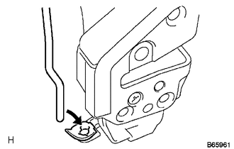
Insert the open rod into the lock and then set it to the door panel.
- NOTICE:
-
Make sure that the outside handle link is securely engaged with the door lock.
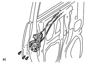
Apply adhesive to the threads of the screws.
- Adhesive:
Toyota Genuine Adhesive 1324, Three Bond 1344 or equivalent
Using a T30 "TORX" socket, install the lock with the 3 screws.
- Torque:
- 5.5 N*m (56 kgf*cm, 49 in.*lbf)
Connect the lock connector.
69217D
10.INSTALL FRONT DOOR OUTSIDE HANDLE COVER
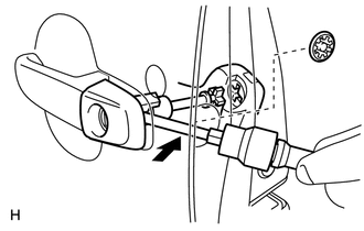
Using a T30 "TORX" socket, install the outside handle cover with the screw.
- Torque:
- 7.0 N*m (71 kgf*cm, 62 in.*lbf)
Install the hole plug.
67404F
11.INSTALL FRONT DOOR FRAME SUB-ASSEMBLY REAR LOWER LH
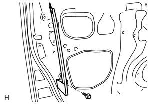
Install the frame with the bolt.
- Torque:
- 7.5 N*m (77 kgf*cm, 66 in.*lbf)
85720C
12.INSTALL POWER WINDOW REGULATOR MOTOR ASSEMBLY LH
Using a T25 "TORX" driver, install the regulator motor with the 3 screws.
- Torque:
- 5.4 N*m (55 kgf*cm, 48 in.*lbf)
- NOTICE:
-
Do not rotate the motor counterclockwise until the window glass installation is completed.
69802
13.INSTALL FRONT DOOR WINDOW REGULATOR SUB-ASSEMBLY LH
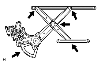
Apply MP grease to the sliding and rotating parts of the window regulator.
- NOTICE:
-
Do not apply grease to the spring of the window regulator.
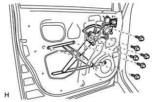
Install the window regulator with the 6 bolts.
- Torque:
- 7.5 N*m (77 kgf*cm, 66 in.*lbf)
- NOTICE:
-
Be careful not to drop the door window regulator as it may become damaged.
Connect the window regulator connector.
68102
14.INSTALL FRONT DOOR GLASS SUB-ASSEMBLY LH
- NOTICE:
-
Do not damage the door glass.
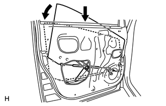
Install the glass run.
Insert the door glass into the door panel along the glass run in the direction indicated by the arrow in the illustration.
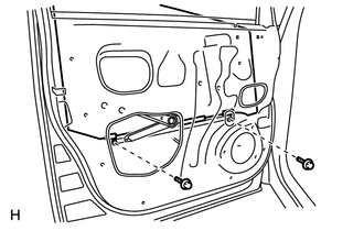
Install the door glass to the window regulator with the 2 bolts.
- Torque:
- 7.5 N*m (77 kgf*cm, 66 in.*lbf)
Reset the power window motor (See page Vehicle Interior>WINDOW / GLASS>POWER WINDOW CONTROL SYSTEM>INITIALIZATION).
Inspect the operation of the power window.
- HINT:
-
When the installation point of the door glass does not match, adjust the regulator position using manual operation.
Connect the power window switch to the wire harness and turn the engine switch on (IG).
Repeat the UP and DOWN operations several times using manual operation.
87940
15.INSTALL OUTER REAR VIEW MIRROR ASSEMBLY LH
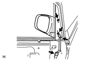
Install the mirror with the 3 nuts.
- Torque:
- 8.0 N*m (82 kgf*cm, 71 in.*lbf)
Connect the mirror connector.
67832
16.INSTALL FRONT DOOR SERVICE HOLE COVER LH
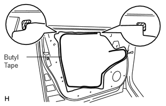
Apply butyl tape to the door panel, as shown in the illustration.
Install the service hole cover.
- HINT:
- ·
When installing the service hole cover, pull out the links and connectors through the service hole cover.
·There should be no wrinkles or folds after attaching the service hole cover.
·After attaching the service hole cover, confirm the sealing condition.
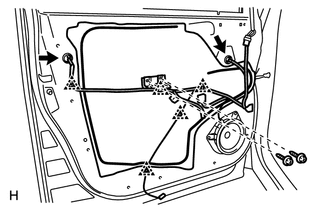
Connect the connectors and clamps.
Install the No. 1 reinforcement with the 2 screws.
67602
17.INSTALL FRONT DOOR TRIM BOARD SUB-ASSEMBLY LH
Install the inside handle with the 3 screws.
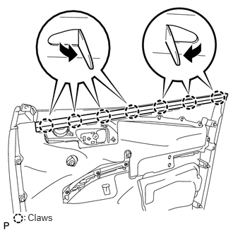
Attach the 7 claws to install the weatherstrip inner.
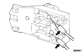
Connect the 2 cables to the inside handle, as shown in the illustration.
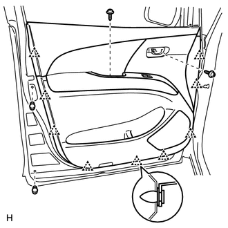
Attach the 9 clips to install the trim board.
Install the 2 screws.
Install the 2 cushion rubbers.
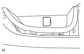
Attach the claw to install the cover.
84040
18.INSTALL MULTIPLEX NETWORK MASTER SWITCH ASSEMBLY (for Driver Side)
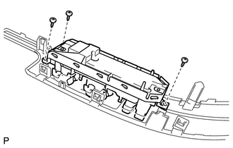
Install the switch to the panel with the 3 screws.
84810
19.INSTALL POWER WINDOW REGULATOR SWITCH ASSEMBLY (for Passenger Side)
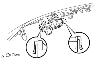
Attach the 2 claws to install the switch to the panel.
74232
20.INSTALL FRONT ARMREST BASE PANEL UPPER LH
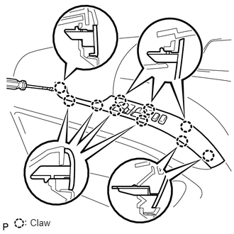
Connect the connector and install the switch to the panel.
Attach the 10 claws to install the panel.
69278B
21.INSTALL FRONT DOOR INSIDE HANDLE BEZEL LH
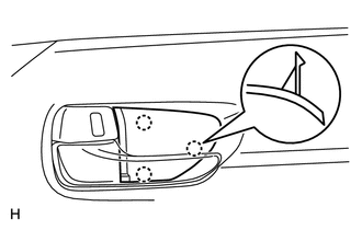
Attach the 3 claws to install the bezel plug.
67492A
22.INSTALL FRONT DOOR LOWER FRAME BRACKET GARNISH LH
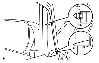
Attach the clip and claw to install the garnish.
28800
23.CONNECT CABLE TO NEGATIVE BATTERY TERMINAL
24.PERFORM INITIALIZATION
Perform initialization (See page General>INTRODUCTION>REPAIR INSTRUCTION>INITIALIZATION).
- NOTICE:
-
Certain systems need to be initialized after disconnecting and reconnecting the cable from the negative (-) battery terminal.
25.CHECK SRS WARNING LIGHT
Check the SRS warning light (See page Vehicle Interior>SUPPLEMENTAL RESTRAINT SYSTEMS>AIRBAG SYSTEM>DIAGNOSIS SYSTEM).