K112 CVT OIL COOLER INSTALLATION
PROCEDURE

 33493B
1.INSTALL OIL COOLER
Install the oil cooler to the continuously variable transaxle with the 3 bolts.
- Torque:
- 12 N*m (120 kgf*cm, 8 ft.*lbf)
2.INSTALL OIL COOLER HOSE (w/o Air Cooled Transmission Oil Cooler)
Install the 4 clamps to the 2 oil cooler hoses.
Install the 2 oil cooler hoses to the oil cooler and continuously variable transaxle assembly and engage the 4 clamps.
- NOTICE:
-
Fully insert the 2 oil cooler hoses until the 2nd rib on each oil cooler pipe.
3.INSTALL OIL COOLER HOSE (w/ Air Cooled Transmission Oil Cooler)
Install the 6 clamps to the 3 outlet No. 1 oil cooler hoses.
Install the 3 outlet No. 1 oil cooler hoses to the outlet oil cooler tube and engage the 3 clamps.
Install the 6 clamps to the 3 inlet oil cooler hoses.
Install the 3 inlet oil cooler hoses to the outlet oil cooler tube and engage the 3 clamps.
Install the 2 oil cooler hoses to the oil cooler and continuously variable transaxle assembly and engage the 4 clamps.
- NOTICE:
-
Fully insert the 2 oil cooler hoses until the 2nd rib on each oil cooler pipe.
Install the 2 oil cooler hoses to the oil cooler tube sub-assembly and engage the 2 clamps.
4.CONNECT WATER BY-PASS HOSE (w/o Air Cooled Transmission Oil Cooler)
Connect the 2 water by-pass hoses to the oil cooler and engage the 2 clamps.
- NOTICE:
-
Fully insert the 2 water by-pass hoses until the 2nd rib on each oil cooler pipe.
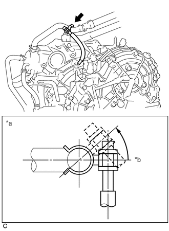
Attach the clamp to the water by-pass hose.
- NOTICE:
- ·
Make sure that the marking on the water by-pass hose is aligned with the center of the clamp.
·Make sure that the breather hose is positioned on the left side of the vehicle.
·Make sure that the breather plug is inclined as shown in the illustration.
·Make sure that the hose is not kinked.
| *a | View from Front of the Vehicle |
| *b | Horizontal Axis |
5.CONNECT WATER BY-PASS HOSE (w/ Air Cooled Transmission Oil Cooler)
Connect the 2 water by-pass hoses to the oil cooler and engage the 2 clamps.
- NOTICE:
-
Fully insert the 2 water by-pass hoses until the 2nd rib on each oil cooler pipe.
16571
6.CONNECT NO. 1 RADIATOR HOSE
7.ADD ENGINE COOLANT
8.ADD CONTINUOUSLY VARIABLE TRANSAXLE FLUID
9.INSPECT FOR COOLANT LEAK
10.INSPECT FOR OIL LEAK
53292A
11.INSTALL UPPER RADIATOR SUPPORT SEAL
51441
12.INSTALL NO. 1 ENGINE UNDER COVER
53702
13.INSTALL FRONT FENDER APRON LH
14.INSTALL FRONT WHEEL LH