U241E AUTOMATIC TRANSMISSION / TRANSAXLE SHIFT LEVER(for RHD) INSTALLATION
PROCEDURE

 1.INSTALL SHIFT LEVER ASSEMBLY
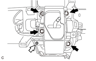
Install the shift lever assembly with the 4 bolts and screw.

|
Bolt |

|
Screw |
- Torque:
- Bolt : 12 N*m (122 kgf*cm, 9 ft.*lbf)
Connect the transmission control switch connector.
Connect the shift lock control ECU sub-assembly connector.
33820B
2.CONNECT TRANSMISSION CONTROL CABLE ASSEMBLY
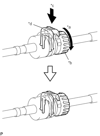
Rotate the nut counterclockwise approximately 180°, and while holding the nut in that position, press in the stopper until it makes 2 "click" sounds.
| *a | Turn |
| *b | Nut |
| *c | Push |
| *d | Stopper |
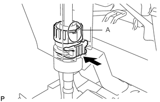
Install the cable outer of the transmission control cable assembly to the shift lever assembly, check that the position of the spring is the same as A shown in the illustration, and press in the stopper.
- HINT:
-
If the stopper cannot be pressed in, slightly rotate the nut clockwise and then press in the stopper.
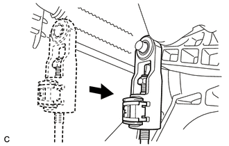
Connect the transmission control cable assembly to the shift lever assembly.
- NOTICE:
- ·
The shift lever should be in N.
·Make sure the transmission control cable assembly is installed to the base of the pin.
3.CONNECT CABLE TO NEGATIVE BATTERY TERMINAL
4.INSPECT SHIFT LEVER POSITION
5.ADJUST SHIFT LEVER POSITION
55475B
6.INSTALL CENTER INSTRUMENT CLUSTER FINISH PANEL GARNISH
55434B
7.INSTALL INSTRUMENT PANEL FINISH PANEL LOWER CENTER
58533C
8.INSTALL FLOOR CARPET COVER CENTER RH
58534E
9.INSTALL FLOOR CARPET COVER CENTER LH
55432B
10.INSTALL INSTRUMENT PANEL FINISH PANEL LOWER
55606
11.INSTALL NO. 1 INSTRUMENT PANEL UNDER COVER SUB-ASSEMBLY
62111C
12.INSTALL COWL SIDE TRIM BOARD RH
67913B
13.INSTALL FRONT DOOR SCUFF PLATE RH
55607
14.INSTALL NO. 2 INSTRUMENT PANEL UNDER COVER SUB-ASSEMBLY
55550
15.INSTALL GLOVE COMPARTMENT DOOR ASSEMBLY
55042B
16.INSTALL NO. 2 INSTRUMENT PANEL BOX DOOR SUB-ASSEMBLY
55041B
17.INSTALL NO. 1 INSTRUMENT PANEL BOX DOOR SUB-ASSEMBLY
18.INSTALL CENTER INSTRUMENT CLUSTER FINISH PANEL ASSEMBLY
33504F
19.INSTALL SHIFT LEVER KNOB SUB-ASSEMBLY
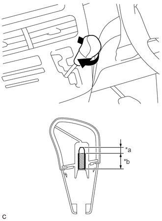
Turn the shift lever knob sub-assembly clockwise until it cannot be turned easily.
| *a | Non-threaded Part |
| *b | Threaded Part |
- HINT:
-
The shift lever knob sub-assembly will become difficult to turn when the lower shift lever assembly contacts the non-threaded part of the shift lever knob sub-assembly.
Turn the shift lever knob sub-assembly clockwise an additional 360° or more to install it as shown in the illustration.
- NOTICE:
-
Make sure to only turn the shift lever knob sub-assembly clockwise when adjusting the installation position.
33554H
20.INSTALL SHIFT LOCK RELEASE BUTTON COVER
Engage the 2 claws to install the shift lock release button cover to the heater control and accessory assembly.
21.PERFORM INITIALIZATION
Perform initialization (see page General>INTRODUCTION>REPAIR INSTRUCTION>INITIALIZATION).
- NOTICE:
-
Certain systems need to be initialized after disconnecting and reconnecting the cable from the negative (-) battery terminal.