INTERIOR ROOF HEADLINING INSTALLATION
PROCEDURE

 1.INSTALL FASTENER HOOK (w/o Sliding Roof)
Install the 7 hooks.
63341
2.INSTALL ROOF NO. 1 SILENCER PAD (w/o Sliding Roof)
Install the silencer pad.
63342
3.INSTALL ROOF NO. 2 SILENCER PAD (w/o Sliding Roof)
Install the 3 silencer pads.
82171
4.INSTALL ROOF NO. 1 WIRE
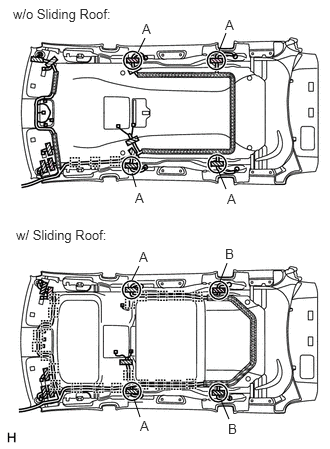
Only when replacing the roof headlining:
w/o Sliding Roof:
Pass the roof wire between the duct and roof headlining at the 4 areas labeled A in the illustration.
- NOTICE:
-
Do not remove the duct when performing this procedure, as it is part of the roof headlining.
Attach the 7 wire harness clamps and install the tape.
Align the marking, and then install the wire harness with double-sided tape.
- NOTICE:
-
The roof wire harness should be attached securely.
- HINT:
-
Be careful that dirt or foreign objects do not stick to the adhesive part when peeling off the double-sided tape.
w/ Sliding Roof:
Pass the roof wire between the duct and roof headlining at the 2 areas labeled A in the illustration.
- NOTICE:
-
Do not remove the duct when performing this procedure, as it is part of the roof headlining.
Pass the roof wire above the duct at the 2 areas labeled B in the illustration.
Attach the 21 wire harness clamps and install the tape.
Align the marking, and then install the wire harness with double-sided tape.
- NOTICE:
-
The roof wire harness should be attached securely.
- HINT:
-
Be careful that dirt or foreign objects do not stick to the adhesive part when peeling off the double-sided tape.
Install the washer hose.
86101
5.INSTALL NO. 2 ANTENNA CORD SUB-ASSEMBLY
86160Q
6.INSTALL ROOF SPEAKER ASSEMBLY
81340
7.INSTALL VANITY LIGHT ASSEMBLY
81290
8.INSTALL ROOM NO. 3 LIGHT ASSEMBLY
81250
9.INSTALL ROOM NO. 2 LIGHT ASSEMBLY
63310
10.INSTALL ROOF HEADLINING ASSEMBLY
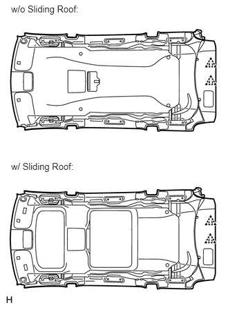
Install the headlining with the hooks and 2 clips.
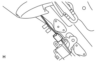
Connect the antenna cord connector to the rear pillar RH.
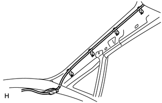
Connect the antenna cord connector to the front pillar RH.
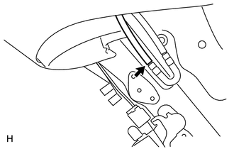
Connect the washer hose.
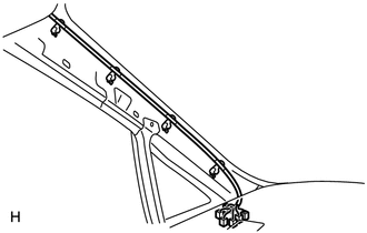
Connect the 6 roof wire connectors.
74610A
11.INSTALL ASSIST GRIP SUB-ASSEMBLY
- HINT:
-
Use the same procedure for the other assist grip.
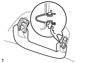
Attach the 4 claws to install the assist grip.
74612
12.INSTALL ASSIST GRIP COVER
- HINT:
-
Use the same procedure for the other assist grip cover.
Attach the 4 claws to install the 2 assist grip covers.
81260A
13.INSTALL MAP LIGHT ASSEMBLY
87820A
14.INSTALL INNER REAR CONVERSATION MIRROR ASSEMBLY
84010A
15.INSTALL COOLER CONTROL SWITCH SUB-ASSEMBLY
86680A
16.INSTALL TELEVISION DISPLAY ASSEMBLY (w/ Television Display)
86295
17.INSTALL TELEVISION BASE (w/ Television Display)
74348
18.INSTALL VISOR HOLDER
74320
19.INSTALL VISOR ASSEMBLY LH
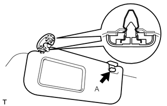
Attach the 2 claws to install the visor.
Install portion A of the visor to the visor holder.
Attach the 4 claws to install the visor bracket cover.
74310
20.INSTALL VISOR ASSEMBLY RH
- HINT:
-
Use the same procedures described for the LH side.
73139B
21.INSTALL SEAT BELT ANCHOR COVER
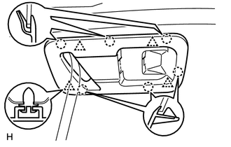
Attach the 6 claws and 4 clips to install the cover.
88566A
22.INSTALL NO. 1 COOLER AIR DUCT
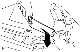
Install the air duct.
Attach the 2 claws to install the plate.
62452C
23.INSTALL REAR ROOF SIDE RAIL GARNISH LH
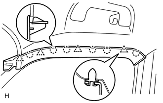
Attach the 6 claws and 4 clips to install the garnish.
62451C
24.INSTALL REAR ROOF SIDE RAIL GARNISH RH
- HINT:
-
Use the same procedures described for the LH side.
62472A
25.INSTALL INNER ROOF SIDE GARNISH LH
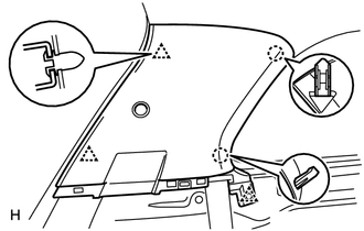
Attach the 2 claws and 3 clips to install the garnish.
Connect the rear No. 2 seat outer belt's shoulder anchor.
Connect the shoulder anchor with the bolt.
- Torque:
- 42 N*m (428 kgf*cm, 31 ft.*lbf)
Install the anchor cover.
62471A
26.INSTALL INNER ROOF SIDE GARNISH RH
- HINT:
-
Use the same procedures described for the LH side.
62639A
27.INSTALL QUARTER PILLAR GARNISH LH (for Captain Seat Type)
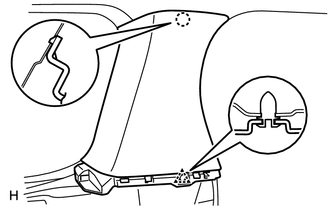
Attach the claw and clip to install the garnish.
62639A
28.INSTALL QUARTER PILLAR GARNISH LH (for Except Captain Seat Type)
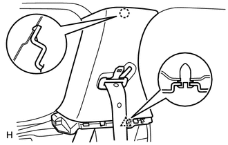
Pass the rear No. 1 seat outer belt's shoulder anchor through the garnish.
Attach the claw and clip to install the garnish.
62638A
29.INSTALL QUARTER PILLAR GARNISH RH (for Captain Seat Type)
- HINT:
-
Use the same procedures described for the LH side.
62638A
30.INSTALL QUARTER PILLAR GARNISH RH (for Except Captain Seat Type)
- HINT:
-
Use the same procedures described for the LH side.
64740A
31.INSTALL DECK TRIM SIDE PANEL ASSEMBLY LH (for Captain Seat Type)
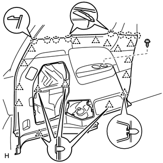
for Power Stowing Seat Type:
Connect the fold seat switch connector.
Attach the 12 clips and 8 claws to install the trim board.
Install the screw and 4 clips.
Connect the rear No. 2 seat belt's floor anchor.
Connect the floor anchor with the bolt.
- Torque:
- 42 N*m (428 kgf*cm, 31 ft.*lbf)
64740A
32.INSTALL DECK TRIM SIDE PANEL ASSEMBLY LH (for Except Captain Seat Type)
Attach the 12 clips and 8 claws to install the trim board.
Install the screw and 4 clips.
Connect the rear No. 1 seat belt's floor anchor.
Connect the floor anchor with the bolt.
- Torque:
- 42 N*m (428 kgf*cm, 31 ft.*lbf)
Connect the rear No. 2 seat belt's floor anchor.
Connect the floor anchor with the bolt.
- Torque:
- 42 N*m (428 kgf*cm, 31 ft.*lbf)
64730B
33.INSTALL DECK TRIM SIDE PANEL ASSEMBLY RH (for Captain Seat Type)
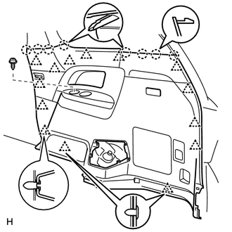
Connect the 3 connectors.
Attach the 12 clips and 8 claws to install the trim board.
Install the screw and 2 clips.
Connect the rear No. 2 seat belt's floor anchor.
Connect the floor anchor with the bolt.
- Torque:
- 42 N*m (428 kgf*cm, 31 ft.*lbf)
64730B
34.INSTALL DECK TRIM SIDE PANEL ASSEMBLY RH (for Except Captain Seat Type)
Connect the 3 connectors.
Attach the 12 clips and 8 claws to install the trim board.
Install the screw and 2 clips.
Connect the rear No. 1 seat belt's floor anchor.
Connect the floor anchor with the bolt.
- Torque:
- 42 N*m (428 kgf*cm, 31 ft.*lbf)
Connect the rear No. 2 seat belt's floor anchor.
Connect the floor anchor with the bolt.
- Torque:
- 42 N*m (428 kgf*cm, 31 ft.*lbf)
64766
35.INSTALL QUARTER TRIM JACK COVER SUB-ASSEMBLY (for LH Side)
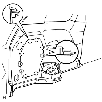
Attach the 9 claws to install the cover.
64735G
36.INSTALL DECK TRIM SIDE SERVICE HOLE COVER LH
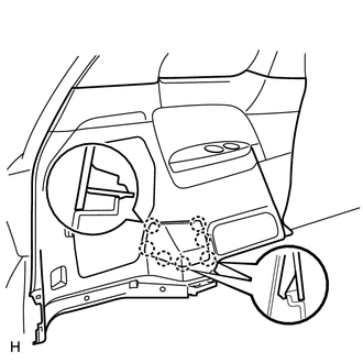
Attach the 7 claws to install the cover.
64735F
37.INSTALL DECK TRIM SIDE SERVICE HOLE COVER RH
Attach the 7 claws to install the cover.
66311B
38.INSTALL ROPE HOOK
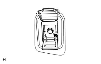
Install the hook with the bolt.
Attach the 2 claws to install the cover.
58625D
39.INSTALL REAR FLOOR NO. 1 MAT PLATE (for Tumble Seat Type, Manual Stowing Seat Type)
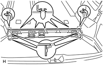
Attach the 6 claws and 5 clips to install the plate.
58625D
40.INSTALL REAR FLOOR NO. 1 MAT PLATE (for Power Stowing Seat Type)
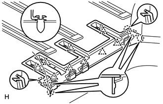
Attach the 6 claws and 9 clips to install the plate.
67939D
41.INSTALL BACK DOOR GARNISH CENTER
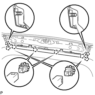
for Type A:
Attach the 8 claws to install the cover.
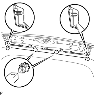
for Type B:
Attach the 6 claws to install the cover.
67935
42.INSTALL BACK DOOR SCUFF PLATE
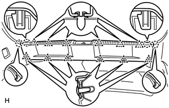
Attach the 4 claws and 6 clips to install the scuff plate.
Install the 6 clips.
67881A
43.INSTALL BACK DOOR WEATHERSTRIP
44.INSTALL REAR NO. 2 SEAT ASSEMBLY LH (for Tumble Seat Type LH Side)
72137E
45.INSTALL NO. 1 SEAT TRACK COVER (for Tumble Seat Type LH Side)
46.INSTALL REAR NO. 2 SEAT ASSEMBLY RH (for Tumble Seat Type RH Side)
72137E
47.INSTALL NO. 1 SEAT TRACK COVER (for Tumble Seat Type RH Side)
79040
48.INSTALL NO. 3 SEAT LEG ASSEMBLY LH (for Power Stowing Seat Type LH Side)
49.INSTALL REAR NO. 2 SEAT ASSEMBLY LH (for Power Stowing Seat Type LH Side)
79273A
50.INSTALL NO. 2 SEAT HINGE COVER (for Power Stowing Seat Type LH Side)
79384
51.INSTALL NO. 3 SEAT LEG COVER REAR LH (for Power Stowing Seat Type LH Side)
79236B
52.INSTALL NO. 2 SEAT LEG COVER LH (for Power Stowing Seat Type LH Side)
79030
53.INSTALL NO. 3 SEAT LEG ASSEMBLY RH (for Power Stowing Seat Type RH Side)
54.INSTALL REAR NO. 2 SEAT ASSEMBLY RH (for Power Stowing Seat Type RH Side)
79273
55.INSTALL NO. 2 SEAT HINGE COVER (for Power Stowing Seat Type RH Side)
79374
56.INSTALL NO. 3 SEAT LEG COVER REAR RH (for Power Stowing Seat Type RH Side)
79236A
57.INSTALL NO. 2 SEAT LEG COVER (for Power Stowing Seat Type RH Side)
72906
58.INSTALL 3RD SEAT LINK SUB-ASSEMBLY LH (for Manual Stowing Seat Type LH Side)
59.INSTALL REAR NO. 2 SEAT ASSEMBLY LH (for Manual Stowing Seat Type LH Side)
79273A
60.INSTALL NO. 2 SEAT HINGE COVER (for Manual Stowing Seat Type LH Side)
79236A
61.INSTALL NO. 2 SEAT LEG COVER (for Manual Stowing Seat Type LH Side)
79236B
62.INSTALL NO. 2 SEAT LEG COVER LH (for Manual Stowing Seat Type LH Side)
79384
63.INSTALL NO. 3 SEAT LEG COVER REAR LH (for Manual Stowing Seat Type LH Side)
64.INSTALL REAR NO. 2 SEAT ASSEMBLY RH (for Manual Stowing Seat Type RH Side)
79273A
65.INSTALL NO. 2 SEAT HINGE COVER (for Manual Stowing Seat Type RH Side)
79236A
66.INSTALL NO. 2 SEAT LEG COVER (for Manual Stowing Seat Type RH Side)
79236B
67.INSTALL NO. 2 SEAT LEG COVER LH (for Manual Stowing Seat Type RH Side)
79374
68.INSTALL NO. 3 SEAT LEG COVER REAR RH (for Manual Stowing Seat Type RH Side)
64420A
69.INSTALL LUGGAGE ROOM BOX LID ASSEMBLY (for Tumble Seat Type, Manual Stowing Seat Type)
62412
70.INSTALL CENTER PILLAR GARNISH LH
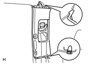
Pass the front seat outer belt's shoulder anchor through the garnish.
Attach the claw and clip to install the garnish.
62411
71.INSTALL CENTER PILLAR GARNISH RH
- HINT:
-
Use the same procedures described for the LH side.
74603C
72.INSTALL ASSIST GRIP SUB-ASSEMBLY
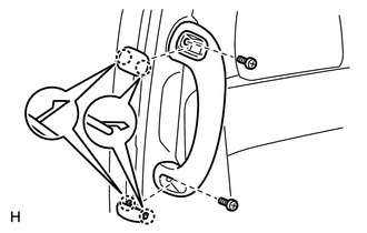
Install the assist grip with the 2 screws.
74617A
73.INSTALL ASSIST GRIP PLUG
Attach the 4 claws to install the 2 assist grip plugs.
62414A
74.INSTALL CENTER PILLAR GARNISH LOWER LH
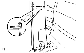
Attach the 2 claws to install the garnish.
Connect the front seat outer belt's floor anchor.
Connect the floor anchor with the bolt.
- Torque:
- 42 N*m (428 kgf*cm, 31 ft.*lbf)
Install the anchor cover.
62413A
75.INSTALL CENTER PILLAR GARNISH LOWER RH
- HINT:
-
Use the same procedures described for the LH side.
67872A
76.INSTALL NO. 1 SLIDE DOOR WEATHERSTRIP LH
67871E
77.INSTALL NO. 1 SLIDE DOOR WEATHERSTRIP RH
67918E
78.INSTALL REAR DOOR SCUFF PLATE LH
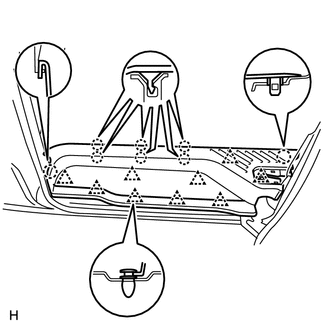
Attach the 8 claws and 9 clips to install the scuff plate.
67917C
79.INSTALL REAR DOOR SCUFF PLATE RH
Attach the 8 claws and 9 clips to install the scuff plate.
67918D
80.INSTALL REAR DOOR SCUFF PLATE LH
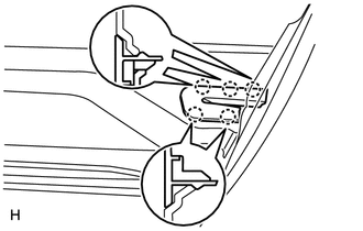
Attach the 5 claws to install the plate.
67911A
81.INSTALL REAR DOOR SCUFF PLATE RH
Attach the 5 claws to install the plate.
62212
82.INSTALL FRONT PILLAR GARNISH LH (w/o Curtain Shield Airbag)
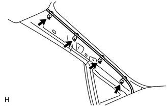
Install the 4 wire harness clamps.
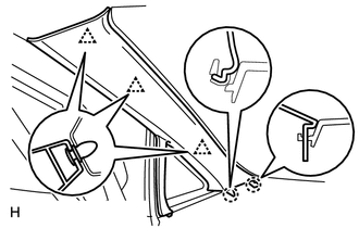
Attach the 2 claws and 3 clips to install the garnish.
62212
83.INSTALL FRONT PILLAR GARNISH LH (w/ Curtain Shield Airbag)
Remove the piece of cloth or nylon.
Install the 4 wire harness clamps.
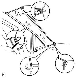
Install 2 new clips labeled B to the vehicle body.
Set the 2 claws of the pillar garnish to the area labeled C.
Insert the tips of the clips labeled B into the pillar garnish's holes.
Using needle-nose pliers, rotate the tips of the clips labeled B 90°. Then push the pillar garnish toward the vehicle body to attach the base of the 2 clips labeled B and the clip labeled A.
62211
84.INSTALL FRONT PILLAR GARNISH RH (w/o Curtain Shield Airbag)
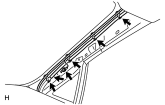
Install the 4 antenna cord clamps.
Install the bolt to connect the ground wire.
Connect the washer hose.
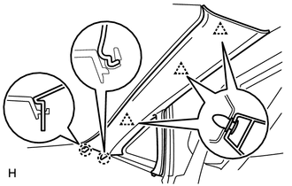
Attach the 2 claws and 3 clips to install the garnish.
62211
85.INSTALL FRONT PILLAR GARNISH RH (w/ Curtain Shield Airbag)
Remove the piece of cloth or nylon.
Install the 4 antenna cord clamps.
Install the bolt to connect the ground wire.
Connect the washer hose.
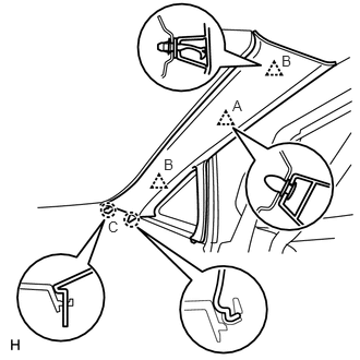
Install 2 new clips labeled B to the vehicle body.
Set the 2 claws of the pillar garnish to the area labeled C.
Insert the tips of the clips labeled B into the pillar garnish's holes.
Using needle-nose pliers, rotate the tips of the clips labeled B 90°. Then push the pillar garnish toward the vehicle body to attach the base of the 2 clips labeled B and the clip labeled A.
62226
86.INSTALL FRONT PILLAR GARNISH LOWER LH
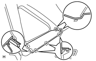
Attach the 7 claws to install the garnish.
62225A
87.INSTALL FRONT PILLAR GARNISH LOWER RH
Attach the 7 claws to install the garnish.
62312C
88.INSTALL FRONT DOOR OPENING TRIM WEATHERSTRIP LH
- NOTICE:
-
After assembling the front door opening trim weatherstrip LH, confirm that there is no floating up or disconnection anywhere around its entire circumference. If there is floating up or disconnection, push the front door opening trim weatherstrip LH to the door while shrinking its opening in such a way that the floating up or disconnected part is grasped and tightened. After assembling the weather strip, confirm again that there is no floating up or disconnection anywhere around its entire circumference.
62311C
89.INSTALL FRONT DOOR OPENING TRIM WEATHERSTRIP RH
- NOTICE:
-
After assembling the front door opening trim weatherstrip RH, confirm that there is no floating up or disconnection anywhere around its entire circumference. If there is floating up or disconnection, push the front door opening trim weatherstrip RH to the door while shrinking its opening in such a way that the floating up or disconnected part is grasped and tightened. After assembling the weather strip, confirm again that there is no floating up or disconnection anywhere around its entire circumference.
62112
90.INSTALL COWL SIDE TRIM BOARD LH
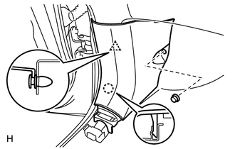
Attach the claw and clip to install the trim board.
Install the cap nut.
62111C
91.INSTALL COWL SIDE TRIM BOARD RH
- HINT:
-
Use the same procedures described for the LH side.
67914B
92.INSTALL FRONT DOOR SCUFF PLATE LH
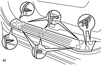
Attach the 10 claws to install the scuff plate.
67913B
93.INSTALL FRONT DOOR SCUFF PLATE RH
Attach the 10 claws to install the scuff plate.
94.CONNECT CABLE TO NEGATIVE BATTERY TERMINAL
- NOTICE:
-
When disconnecting the cable, some systems need to be initialized after the cable is reconnected (See page General>INTRODUCTION>REPAIR INSTRUCTION>INITIALIZATION).
95.INSPECT REAR NO. 2 SEAT STOWING FUNCTION (for Power Stowing Seat Type)