SUSPENSION FRONT LOWER SUSPENSION ARM(for 2GR-FE) INSTALLATION
PROCEDURE

 1.INSTALL FRONT SUSPENSION LOWER NO. 1 ARM SUB-ASSEMBLY
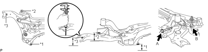
Position the front suspension crossmember sub-assembly on a level surface.
- NOTICE:
-
Position the crossmember with the front suspension member brace front LH and RH mounted.
Using vernier calipers, measure height*1 and *2.
Check that height*2 is lower than *1 by 10 mm.
Position the front suspension lower No. 1 arm so that height*3 is the same as *1.
Tighten the bolt A.
- Torque:
- 233 N*m (2376 kgf*cm, 172 ft.*lbf)
Temporarily install the bolt and nut.
51201
2.INSTALL FRONT SUSPENSION CROSSMEMBER SUB-ASSEMBLY
Raise the front suspension crossmember sub-assembly with a transmission jack.
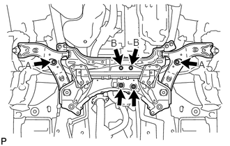
Temporarily install the front suspension crossmember sub-assembly with 2 bolts A, the 2 bolts B and 2 nuts.
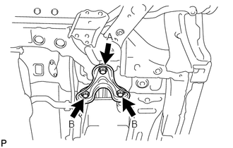
Temporarily install the front suspension member brace sub-assembly LH and RH with 2 bolts A and the 4 bolts B.
Alternately insert SST into the reference holes on the front suspension crossmember RH and LH while tightening bolts A and B on the LH and RH sides to each specified torque in several steps.
- SST
- 09670-00010
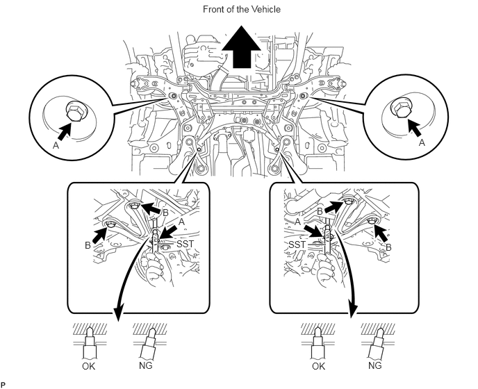
- Torque:
- Bolt A : 137 N*m (1397 kgf*cm, 101 ft.*lbf)
- Bolt B : 93 N*m (948 kgf*cm, 69 ft.*lbf)
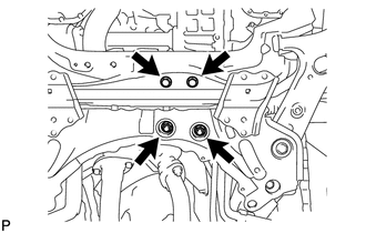
Fully tighten the 2 bolts and 2 nuts.
- Torque:
- 96 N*m (978 kgf*cm, 71 ft.*lbf)
48069
3.CONNECT FRONT SUSPENSION LOWER NO. 1 ARM SUB-ASSEMBLY LH
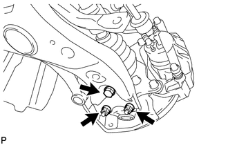
Connect the front suspension lower No. 1 arm LH to the ball joint with the bolt and 2 nuts.
- Torque:
- 93 N*m (948 kgf*cm, 69 ft.*lbf)
48068
4.CONNECT FRONT SUSPENSION LOWER NO. 1 ARM SUB-ASSEMBLY RH
- HINT:
-
Perform the same procedures as for the LH side.
5.CONNECT TIE ROD END SUB-ASSEMBLY LH
6.CONNECT TIE ROD END SUB-ASSEMBLY RH
- HINT:
-
Perform the same procedures as for the LH side.
45260
7.CONNECT NO. 2 STEERING INTERMEDIATE SHAFT ASSEMBLY
45259A
8.INSTALL COLUMN HOLE COVER SILENCER SHEET
51218A
9.INSTALL FRONT SUSPENSION MEMBER REINFORCEMENT LH
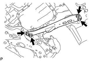
Install the front suspension member reinforcement LH with the 4 bolts.
- Torque:
- 96 N*m (979 kgf*cm, 71 ft.*lbf)
51217A
10.INSTALL FRONT SUSPENSION MEMBER REINFORCEMENT RH
- HINT:
-
Perform the same procedures as for the LH side.
48810
11.INSTALL FRONT STABILIZER LINK ASSEMBLY LH
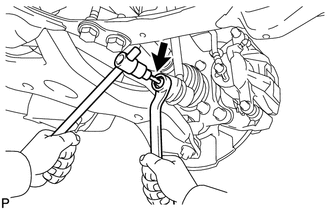
Install the front stabilizer link assembly LH to the front stabilizer bar with the nut.
- Torque:
- 74 N*m (755 kgf*cm, 55 ft.*lbf)
- HINT:
-
If the ball joint turns together with the nut, use a hexagon wrench (6 mm) to hold the stud bolt.
48820B
12.INSTALL FRONT STABILIZER LINK ASSEMBLY RH
- HINT:
-
Perform the same procedures as for the LH side.
53702
13.INSTALL FRONT FENDER APRON SUB-ASSEMBLY LH
53701
14.INSTALL FRONT FENDER APRON SUB-ASSEMBLY RH
51441D
15.INSTALL ENGINE UNDER COVER
51442
16.INSTALL NO. 2 ENGINE UNDER COVER
51441
17.INSTALL NO. 1 ENGINE UNDER COVER
18.INSTALL FRONT WHEEL
- Torque:
- 103 N*m (1050 kgf*cm, 76 ft.*lbf)
19.STABILIZE SUSPENSION
20.FULLY TIGHTEN FRONT SUSPENSION LOWER NO. 1 ARM SUB-ASSEMBLY
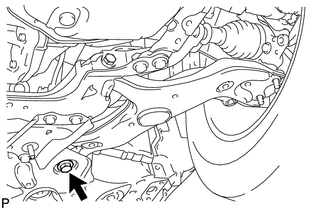
Fully tighten the bolt.
- Torque:
- 214 N*m (2182 kgf*cm, 158 ft.*lbf)
- NOTICE:
-
When removing the bolt, keep the nut from rotating.
21.INSPECT AND ADJUST FRONT WHEEL ALIGNMENT
Inspect and adjust the front wheel alignment (See page Suspension>SUSPENSION>FRONT WHEEL ALIGNMENT>ADJUSTMENT).