POWER STEERING STEERING GEAR INSTALLATION
PROCEDURE

 45510
1.INSTALL STEERING GEAR ASSEMBLY
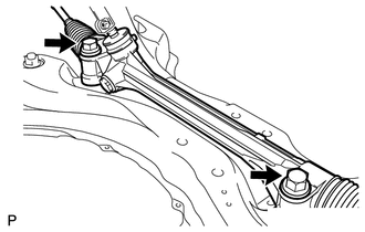
Install the steering gear onto the front suspension crossmember with the 2 bolts and 2 nuts.
- Torque:
- 110 N*m (1122 kgf*cm, 81 ft.*lbf)
- NOTICE:
-
Keep the nut from rotating while turning the bolt.
45221
2.INSTALL STEERING INTERMEDIATE SHAFT
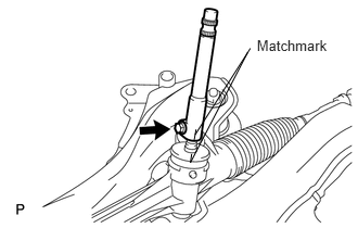
Align the matchmarks and install the intermediate shaft onto the steering gear.
- Torque:
- 35 N*m (360 kgf*cm, 26 ft.*lbf)
45025D
3.INSTALL NO. 1 STEERING COLUMN HOLE COVER SUB-ASSEMBLY
Install the column hole cover onto the steering gear with a new clamp.
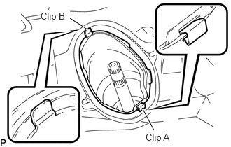
Attach clip B onto the body portion and install the No. 1 hole cover onto the body portion with clip A.
- NOTICE:
-
Make sure that the lip portion of the No. 1 hole cover is not damaged.
51201
4.INSTALL FRONT SUSPENSION CROSSMEMBER SUB-ASSEMBLY (for 2AZ-FE)
51201
5.INSTALL FRONT SUSPENSION CROSSMEMBER SUB-ASSEMBLY (for 2GR-FE)
6.INSTALL FRONT AXLE ASSEMBLY LH
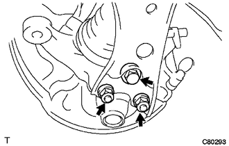
Push down the front suspension lower arm, and install the front lower ball joint LH with the bolt and 2 nuts.
- Torque:
- 93 N*m (948 kgf*cm, 69 ft.*lbf)
7.INSTALL FRONT AXLE ASSEMBLY RH
45407
8.INSTALL TIE ROD END SUB-ASSEMBLY LH
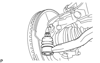
Connect the tie rod end onto the steering knuckle with the castle nut.
- Torque:
- 49 N*m (500 kgf*cm, 36 ft.*lbf)
- NOTICE:
-
If the holes for the clip are not aligned, tighten the nut up to 60° further.
Install a new cotter pin.
45046
9.INSTALL TIE ROD END SUB-ASSEMBLY RH
- HINT:
-
Use the same procedure for the RH side as for the LH side.
48810
10.INSTALL FRONT STABILIZER LINK ASSEMBLY LH
48820B
11.INSTALL FRONT STABILIZER LINK ASSEMBLY RH
- HINT:
-
Use the same procedure for the RH side as for the LH side.
51218A
12.INSTALL FRONT SUSPENSION MEMBER REINFORCEMENT LH
51217A
13.INSTALL FRONT SUSPENSION MEMBER REINFORCEMENT RH
- HINT:
-
Use the same procedure for the RH side as for the LH side.
53702
14.INSTALL FRONT FENDER APRON LH
53701
15.INSTALL FRONT FENDER APRON RH
51441
16.INSTALL NO. 1 ENGINE UNDER COVER
51442
17.INSTALL NO. 2 ENGINE UNDER COVER
45260
18.INSTALL NO. 2 STEERING INTERMEDIATE SHAFT ASSEMBLY
45259A
19.INSTALL COLUMN HOLE COVER SILENCER SHEET
20.INSTALL FRONT WHEEL
28800
21.CONNECT CABLE TO NEGATIVE BATTERY TERMINAL
22. PERFORM INITIALIZATION
Perform initialization (see page General>INTRODUCTION>REPAIR INSTRUCTION>INITIALIZATION).
- NOTICE:
-
Certain systems need to be initialized after disconnecting and reconnecting the cable from the negative (-) battery terminal
23.ADJUST FRONT WHEEL ALIGNMENT
Adjust front wheel alignment (see page Suspension>SUSPENSION>FRONT WHEEL ALIGNMENT>ADJUSTMENT).