BRAKE CONTROL / DYNAMIC CONTROL SYSTEMS ANTI-LOCK BRAKE SYSTEM C1243/43 Deceleration Sensor Stuck Malfunction C1244/44 Open or Short in Deceleration Sensor Circuit C1245/45 Deceleration Sensor Output Malfunction
DESCRIPTION
| DTC No. | DTC Detection Condition | Trouble Area |
|---|---|---|
| C1243/43 | While the vehicle is being driven and the brake pedal is not depressed, the deceleration sensor value remains 3.9 m/s2 or more for 20 seconds or more. | ·
Deceleration sensor ·
Deceleration sensor circuit ·
Brake actuator assembly (Skid control ECU) |
| C1244/44 | Either of the following is detected:
1.
Deceleration sensor output voltage is 4.7 V or more, or 0.3 V or less for 1 second or more. 2.
Deceleration sensor power supply voltage is less than 4.7 V, or more than 5.3 V for 60 seconds or more. |
·
Deceleration sensor ·
Deceleration sensor circuit ·
Brake actuator assembly (Skid control ECU) |
| C1245/45 | Either of the following is detected:
1.
When the vehicle speed is 30 km/h (19 mph) or more, the difference between longitudinal G force calculated from the deceleration sensor value and that calculated from the vehicle speed exceeds 0.15 G for 2 seconds or more. 2.
The change in the deceleration sensor value is 0.05 G or less. |
·
Deceleration sensor ·
Deceleration sensor circuit ·
Brake actuator assembly (Skid control ECU) |
WIRING DIAGRAM
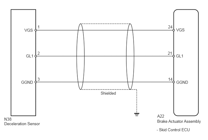
CAUTION / NOTICE / HINT
- HINT:
-
When replacing the brake actuator assembly (skid control ECU) or deceleration sensor, perform deceleration sensor zero point calibration and CVT oil pressure calibration (See page Drivetrain>K112 (CVT)>CONTINUOUSLY VARIABLE TRANSAXLE SYSTEM>INITIALIZATION).
PROCEDURE
Connect the intelligent tester to the DLC3.
Turn the engine switch on (IG).
Select the Data List using the intelligent tester (See page Brake>BRAKE CONTROL / DYNAMIC CONTROL SYSTEMS>ANTI-LOCK BRAKE SYSTEM>DATA LIST / ACTIVE TEST).
| Tester Display | Measurement Item/Range | Normal Condition | Diagnostic Note |
|---|---|---|---|
| Deceleration sensor | Deceleration sensor reading / Min.: -18.525 m/s2, Max.: 18.387 m/s2 | - | During deceleration/acceleration: Changes continuously |
Park the vehicle on a level surface and inspect the deceleration sensor output value.
- OK:
0 m/s2
Drive the vehicle at low speeds, quickly depress the brake pedal and check the change in the deceleration sensor output value.
- OK:
The output value changes in proportion to the longitudinal inclination of the vehicle.
If the deceleration sensor output value does not change while braking, perform the following procedure:
Remove the deceleration sensor (See page Brake>BRAKE CONTROL / DYNAMIC CONTROL SYSTEMS>DECELERATION SENSOR>REMOVAL).
Tilt the sensor in a longitudinal direction and check the change in the output value.
- OK:
The output value changes in proportion to the inclination of the sensor.
OK
NG
Clear the DTCs (See page Brake>BRAKE CONTROL / DYNAMIC CONTROL SYSTEMS>ANTI-LOCK BRAKE SYSTEM>DTC CHECK / CLEAR).
Turn the engine switch off.
Start the engine.
Perform a road test.
Check if the same DTC is output (See page Brake>BRAKE CONTROL / DYNAMIC CONTROL SYSTEMS>ANTI-LOCK BRAKE SYSTEM>DTC CHECK / CLEAR).
- Result:
Result Proceed to DTC is not output A DTC is output B
A
(See pageGeneral>INTRODUCTION>HOW TO TROUBLESHOOT ECU CONTROLLED SYSTEMS>HOW TO PROCEED WITH TROUBLESHOOTING)
B
(See pageBrake>BRAKE CONTROL / DYNAMIC CONTROL SYSTEMS>BRAKE ACTUATOR(for 2AZ-FE without VSC)>REMOVAL)
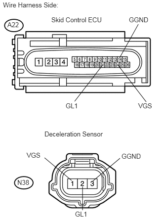
Turn the engine switch off.
Disconnect the A22 skid control ECU connector.
Disconnect the N38 deceleration sensor connector.
Measure the resistance according to the value(s) in the table below.
- Standard Resistance:
Tester Connection Condition Specified Condition A22-21 (GL1) - N38-2 (GL1) Always Below 1 Ω A22-21 (GL1) - Body ground Always 10 kΩ or higher A22-24 (VGS) - N38-1 (VGS) Always Below 1 Ω A22-24 (VGS) - Body ground Always 10 kΩ or higher A22-14 (GGND) - N38-3 (GGND) Always Below 1 Ω A22-14 (GGND) - Body ground Always 10 kΩ or higher
OK
NG
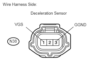
Reconnect the A22 skid control ECU connector.
Measure the voltage according to the value(s) in the table below.
- Standard Voltage:
Tester Connection Condition Specified Condition N38-1 (VGS) - N38-3 (GGND) Engine switch on (IG) 4.5 to 5.5 V
OK
NG
(See pageBrake>BRAKE CONTROL / DYNAMIC CONTROL SYSTEMS>BRAKE ACTUATOR(for 2AZ-FE without VSC)>REMOVAL)
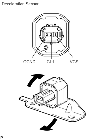
Remove the deceleration sensor.
Connect 3 dry cell batteries of 1.5 V in series.
Connect the 1 (VGS) terminal to the batteries' positive (+) terminal and the 3 (GGND) terminal to the batteries' negative (-) terminal.
Apply about 4.5 V between the 1 (VGS) and 3 (GGND) terminals.
- NOTICE:
-
Do not apply voltage of 6.0 V or more to terminals 1 (VGS) and 3 (GGND).
Check the output voltage of the 2 (GL1) terminal when the sensor is tilted forward and backward.
| Tester Connection | Condition | Specified Condition |
|---|---|---|
| 2 (GL1) - Batteries' negative (-) terminal | Horizontal | About 2.3 V |
| 2 (GL1) - Batteries' negative (-) terminal | Lean forward and backward | Changes between 0.4 and 4.0 V |
- HINT:
- ·
If the sensor is tilted too much, it may show the wrong value.
·If dropped, the sensor should be replaced with a new one.
·Check and ensure the correct installation direction of the deceleration sensor.
OK
NG
Install the deceleration sensor.
Reconnect the N38 deceleration sensor connector.
Clear the DTCs (See page Brake>BRAKE CONTROL / DYNAMIC CONTROL SYSTEMS>ANTI-LOCK BRAKE SYSTEM>DTC CHECK / CLEAR).
Turn the engine switch off.
Start the engine.
Perform a road test.
Check if the same DTC is output (See page Brake>BRAKE CONTROL / DYNAMIC CONTROL SYSTEMS>ANTI-LOCK BRAKE SYSTEM>DTC CHECK / CLEAR).
- Result:
Result Proceed to DTC is not output A DTC is output B
A
(See pageGeneral>INTRODUCTION>HOW TO TROUBLESHOOT ECU CONTROLLED SYSTEMS>HOW TO PROCEED WITH TROUBLESHOOTING)
B
(See pageBrake>BRAKE CONTROL / DYNAMIC CONTROL SYSTEMS>BRAKE ACTUATOR(for 2AZ-FE without VSC)>REMOVAL)