Home › Brake › BRAKE CONTROL / DYNAMIC CONTROL SYSTEMS › VEHICLE STABILITY CONTROL SYSTEM › 2013.04–2014.09
RM24M0E _54 Brake _059583 BRAKE CONTROL / DYNAMIC CONTROL SYSTEMS _0292158 VEHICLE STABILITY CONTROL SYSTEM J

BRAKE CONTROL / DYNAMIC CONTROL SYSTEMS  VEHICLE STABILITY CONTROL SYSTEM  ABS Warning Light Remains ON  


DESCRIPTION

If any of the following conditions are detected, the ABS warning light remains on:

1.

The ECU connectors are disconnected from the skid control ECU.

2.

There is a malfunction in the skid control ECU internal circuit.

3.

There is an open or short in the wire harness between the combination meter and the skid control ECU.


HINT:

The intelligent tester may not be used when there is a malfunction in the skid control ECU.


WIRING DIAGRAM
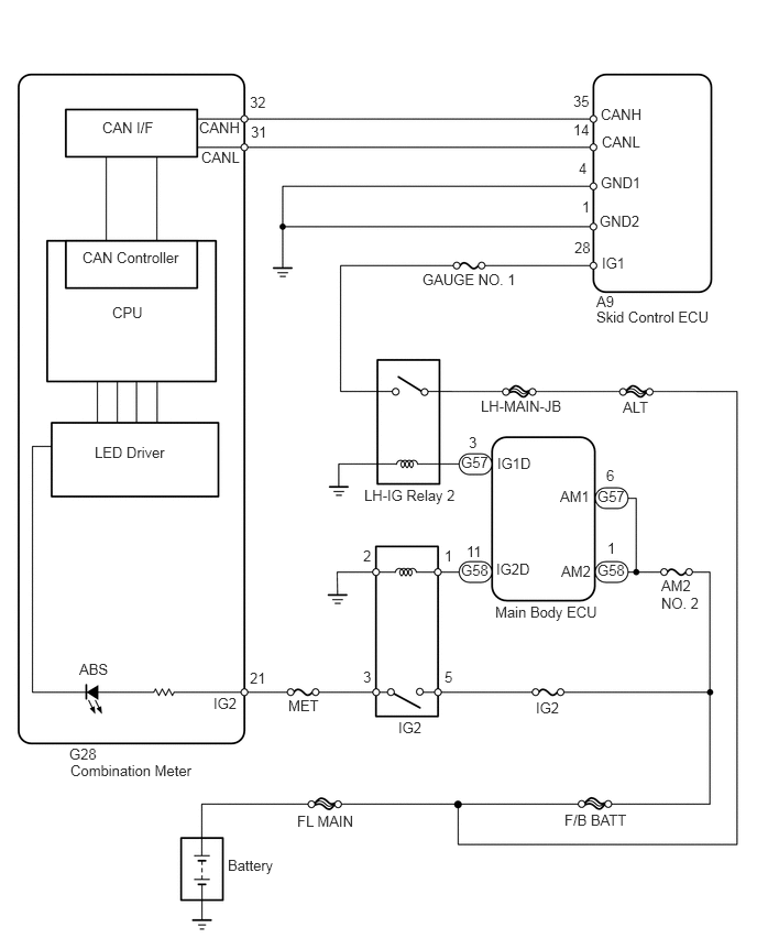
C139058E11
0.667,7.208 1.917,7.354 1.25,0.146 10 false Combination Meter 5.646,2.771 5.865,2.948 0.219,0.177 10 false A9 5.688,1 6.198,1.167 0.51,0.167 10 false CANH 5.698,1.26 6.198,1.458 0.5,0.198 10 false CANL 4.688,5.708 5.74,5.927 1.052,0.219 10 false Main Body ECU 0.969,1.125 1.542,1.302 0.573,0.177 10 false CAN I/F 0.781,2.354 1.771,2.563 0.99,0.208 10 false CAN Controller 1.063,2.875 1.427,3.073 0.365,0.198 10 false CPU 0.896,4.198 1.698,4.396 0.802,0.198 10 false LED Driver 0.75,6.25 1.156,6.438 0.406,0.188 10 false ABS 5.688,1.646 6.177,1.854 0.49,0.208 10 false GND1 5.677,2.01 6.156,2.208 0.479,0.198 10 false GND2 5.698,2.406 5.979,2.552 0.281,0.146 10 false IG1 4,2.563 4.969,2.719 0.969,0.156 10 false GAUGE NO. 1 3.448,4.604 4.5,4.781 1.052,0.177 10 false LH-IG Relay 2 3.771,6.802 4.125,7 0.354,0.198 10 false IG2 2.813,7.688 3.427,7.875 0.615,0.188 10 false FL MAIN 2.156,8.104 2.771,8.292 0.615,0.188 10 false Battery 2.729,6.594 3.083,6.781 0.354,0.188 10 false MET 5.896,3.771 6.26,3.948 0.365,0.177 10 false ALT 5.073,6.615 5.354,6.792 0.281,0.177 10 false IG2 5.302,4.615 5.646,4.823 0.344,0.208 10 false AM1 4.698,5.302 5.052,5.5 0.354,0.198 10 false IG2D 5.313,5.323 5.656,5.531 0.344,0.208 10 false AM2 6.26,5.458 6.698,5.823 0.438,0.365 10 false AM2 NO. 2 4.708,4.302 5.063,4.5 0.354,0.198 10 false IG1D 1.885,1.125 2.396,1.292 0.51,0.167 10 false CANH 1.906,1.406 2.406,1.604 0.5,0.198 10 false CANL 2.021,6.573 2.292,6.76 0.271,0.188 10 false IG2 2.365,6.333 2.594,6.542 0.229,0.208 10 false 21 3.438,6.323 3.604,6.531 0.167,0.208 10 false 3 4.438,4.104 4.604,4.313 0.167,0.208 10 false 3 4.417,5.135 4.604,5.344 0.188,0.208 10 false 11 4.208,6.323 4.375,6.531 0.167,0.208 10 false 5 4.208,5.177 4.375,5.385 0.167,0.208 10 false 1 5.75,5.104 5.917,5.26 0.167,0.156 10 false 1 5.51,1.875 5.677,2.083 0.167,0.208 10 false 1 5.74,4.417 5.906,4.583 0.167,0.167 10 false 6 3.438,5.177 3.604,5.385 0.167,0.208 10 false 2 5.344,7.677 5.969,7.823 0.625,0.146 10 false F/B BATT 5.656,4.615 5.979,4.781 0.323,0.167 10 false G57 5.656,5.313 5.979,5.479 0.323,0.167 10 false G58 4.365,5.313 4.688,5.479 0.323,0.167 10 false G58 4.365,4.292 4.688,4.458 0.323,0.167 10 false G57 4.552,3.76 5.406,3.948 0.854,0.188 10 false LH-MAIN-JB 2.375,1.167 2.563,1.323 0.188,0.156 10 false 31 2.365,0.885 2.552,1.042 0.188,0.156 10 false 32 0.656,7.052 0.948,7.229 0.292,0.177 10 false G28 5.427,0.875 5.615,1.063 0.188,0.188 10 false 35 5.438,2.26 5.625,2.448 0.188,0.188 10 false 28 5.427,1.146 5.667,1.333 0.24,0.188 10 false 14 5.479,1.51 5.667,1.698 0.188,0.188 10 false 4 5.646,2.917 6.865,3.094 1.219,0.177 10 false Skid Control ECU

PROCEDURE

1.CHECK CAN COMMUNICATION SYSTEM
a.

Check if the CAN communication system DTC is output (see page Power Source / Network>CAN COMMUNICATION>CAN COMMUNICATION SYSTEM>DIAGNOSIS SYSTEM).

Result
Result Proceed to
DTC is not output A
DTC is output B


A

2.INSPECT SKID CONTROL ECU CONNECTOR

B

2.INSPECT SKID CONTROL ECU CONNECTOR
a.

Check if the skid control ECU connector is properly installed.

OK:

The skid control ECU connector is properly installed.


OK

3.CHECK WIRE HARNESS (SKID CONTROL ECU - BATTERY AND BODY GROUND)

NG

CONNECT CONNECTOR TO ECU SECURELY

3.CHECK WIRE HARNESS (SKID CONTROL ECU - BATTERY AND BODY GROUND)
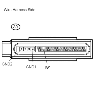
a.
U189325E02
0.76,1.771 0.323,2.188 false 1.573,1.802 1.688,2.292 false 1.177,1.771 1.146,2.292 false 0.135,0.26 1.427,0.406 1.292,0.146 10 false Wire Harness Side: 0.469,0.875 0.667,1.021 0.198,0.146 10 false A9 1.604,2.323 1.917,2.51 0.313,0.188 10 false IG1 0.927,2.313 1.375,2.49 0.448,0.177 10 false GND1 0.063,2.208 0.51,2.385 0.448,0.177 10 false GND2

Disconnect the A9 ECU connector.


b.

Measure the resistance of the wire harness side connector.

Standard resistance:
Tester Connection Specified Condition
A9-4 (GND1) - Body ground Below 1 Ω
A9-1 (GND2) - Body ground Below 1 Ω


c.

Measure the voltage of the wire harness side connector.

Standard voltage:
Tester Connection Condition Specified Condition
A9-28 (IG1) - Body ground Engine switch on (IG) 10 to 14 V


OK

4.PERFORM ACTIVE TEST USING INTELLIGENT TESTER (ABS WARNING LIGHT)

NG

REPAIR OR REPLACE HARNESS OR CONNECTOR

4.PERFORM ACTIVE TEST USING INTELLIGENT TESTER (ABS WARNING LIGHT)
a.

Select the Active Test, generate a control command, and then check that the ABS warning light operates.

ABS/VSC/TRC
Tester Display Test Part Control Range Diagnostic Notes
ABS Warning Light ABS warning light Warning light ON/OFF Observe combination meter

OK:

The ABS warning light is turned on or off.

Result
Result Proceed to
OK (for 2AZ-FE) A
OK (for 2GR-FE) B
NG C


HINT:

When the ABS warning light remains illuminated, opens in the wire harness of the combination meters or abnormalities in the meter circuit should be considered.


A

B

REPLACE ABS AND TRACTION ACTUATOR ASSEMBLY

C