Fuel Pump Control Circuit
Circuit diagnosis · Vehicles built Jul 2007 – Nov 2007
Versions by build date: Jul 2007 – Nov 2007 Dec 2007 – Jul 2009 Aug 2009 – Oct 2010 Nov 2010 – Jul 2012 Aug 2012 – Oct 2012 Nov 2012 – Jul 2014 from Aug 2014
DESCRIPTION
Refer to DTC P0230 (Click here).WIRING DIAGRAM
Refer to DTC P0230 (Click here).INSPECTION PROCEDURE
| 1. CHECK FUEL PUMP OPERATION |
 |
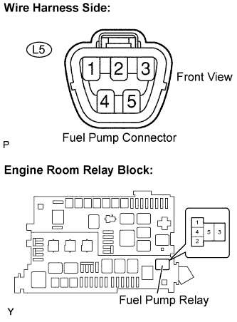
Check if there is pressure in the fuel pipe.
- HINT:
- If there is fuel pressure, you will hear the sound of fuel flowing.
|
OK |
 |
|
|
|
| NG |
|
 |
|
| 2. PERFORM ACTIVE TEST USING INTELLIGENT TESTER (OPERATE CIRCUIT OPENING RELAY) |
|
Connect an intelligent tester to the DLC3.
Turn the ignition switch ON and turn the tester ON.
Select the following menu items: Powertrain / Engine and ECT / Active Test / Fuel Pump/Speed.
Check whether operating sounds can be heard while operating the relay using the tester.
- OK:
- Operating sounds can be heard from relay.
|
OK |
|
|
|
|
| NG |
|
|
|
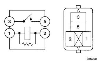
| 3. INSPECT CIRCUIT OPENING RELAY |
|
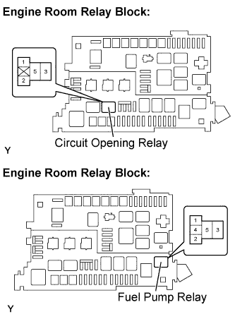
Remove the circuit opening relay from the engine room relay block.
Check the circuit opening relay resistance.
- Standard Resistance:
Tester Connections
|
Specified Conditions
|
3 - 5
|
10 kΩ or higher
|
3 - 5
|
Below 1 Ω
(when battery voltage applied to terminals 1 and 2)
|
Reinstall the circuit opening relay.
|
NG |
 |
|
| REPLACE CIRCUIT OPENING RELAY |
|
|
| OK |
|
|
|
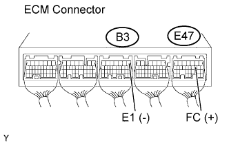
| 4. INSPECT ECM (FC VOLTAGE) |
|
Turn the ignition switch ON.
Measure the voltage between the terminals of the B3 and E47 ECM connectors.
- Standard Voltage:
Tester Connections
|
Specified Conditions
|
FC (E47-10) - E1 (B3-1)
|
11 to 14 V
|
|
OK |
|
|
|
|
| NG |
|
 |
|
| REPAIR OR REPLACE HARNESS OR CONNECTOR (ECM - CIRCUIT OPENING RELAY - IGNITION SWITCH) |
|
| 5. INSPECT ECM POWER SOURCE CIRCUIT |
|
Inspect the ECM power source circuit (Click here).
|
NG |
|
|
| REPAIR OR REPLACE HARNESS OR CONNECTOR |
|
|
| OK |
|
|
|
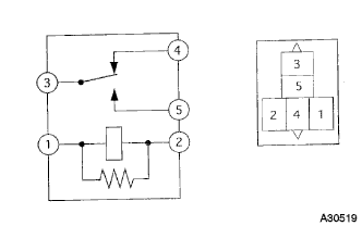
| 6. INSPECT FUEL PUMP RELAY ASSEMBLY |
|
Remove the fuel pump relay from the engine room relay block.
Check the fuel pump relay resistance.
- Standard Resistance:
Tester Connections
|
Specified Conditions
|
3 - 4
|
Below 1 Ω
|
3 - 5
|
10 kΩ or higher
|
3 - 4
|
10 kΩ or higher
(when battery voltage applied to terminals 1 and 2)
|
3 - 5
|
Below 1 Ω
(when battery voltage applied to terminals 1 and 2)
|
Reinstall the fuel pump relay.
|
NG |
|
|
| REPLACE FUEL PUMP RELAY ASSEMBLY |
|
|
| OK |
|
|
|
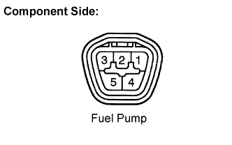
| 7. INSPECT FUEL PUMP ASSEMBLY |
|
Inspect the fuel pump resistance.
Measure the resistance between terminals 4 and 5.
- Standard Resistance:
- 0.2 to 3.0 Ω at 20°C (68°F)
Inspect the fuel pump operation.
Apply battery voltage to both terminals. Check that the pump operates.
- NOTICE:
- These tests must be done quickly (within 10 seconds) to prevent the coil from burning out.
- Keep the fuel pump as far away from the battery as possible.
- Always do the switching at the battery side.
|
NG |
|
|
|
|
| OK |
|
|
|
| 8. CHECK HARNESS AND CONNECTOR (FUEL PUMP - FUEL PUMP RELAY, FUEL PUMP - BODY GROUND) |
|
Check the harness and connector between the fuel pump and fuel pump relay.
Disconnect the L5 fuel pump connector.
Remove the fuel pump relay from the engine room relay block.
Check the resistance.
- Standard Resistance (Check for open):
Tester Connections
|
Specified Conditions
|
Fuel pump (L5-4) - Fuel pump relay (4)
|
Below 1 Ω
|
- Standard Resistance (Check for short):
Tester Connections
|
Specified Conditions
|
Fuel pump (L5-4) or Fuel pump relay (4) - Body ground
|
10 kΩ or higher
|
Reconnect the fuel pump connector.
Reinstall the fuel pump relay.
Check the harness and connector between the fuel pump and body ground.
Disconnect the fuel pump connector.
Check the resistance.
- Standard Resistance (Check for open):
Tester Connections
|
Specified Conditions
|
Fuel pump (L5-5) - Body ground
|
Below 1 Ω
|
Reconnect the fuel pump connector.
|
NG |
|
|
| REPAIR OR REPLACE HARNESS OR CONNECTOR |
|
|
| OK |
|
|
|
| 9. CHECK HARNESS AND CONNECTOR (CIRCUIT OPENING RELAY - FUEL PUMP RELAY) |
|
Remove the circuit opening relay from the engine room relay block.
Remove the fuel pump relay from the engine room relay block.
Check the resistance.
- Standard Resistance (Check for open):
Tester Connections
|
Specified Conditions
|
Circuit opening relay (3) - Fuel pump relay (3)
|
Below 1 Ω
|
- Standard Resistance (Check for short):
Tester Connections
|
Specified Conditions
|
Circuit opening relay (3) or Fuel pump relay (3) - Body ground
|
10 kΩ or higher
|
Reinstall the circuit opening relay.
Reinstall the fuel pump relay.
|
NG |
|
|
| REPAIR OR REPLACE HARNESS OR CONNECTOR |
|
|
| OK |
|
|
|
| REPAIR OR REPLACE HARNESS OR CONNECTOR (EFI RELAY - CIRCUIT OPENING RELAY) |
|
| 10. INSPECT FUEL PUMP RELAY ASSEMBLY |
|
Remove the fuel pump relay from the engine room relay block.
Check the fuel pump relay resistance.
- Standard Resistance:
Tester Connections
|
Specified Conditions
|
3 - 4
|
Below 1 Ω
|
3 - 5
|
10 kΩ or higher
|
3 - 4
|
10 kΩ or higher
(when battery voltage applied to terminals 1 and 2)
|
3 - 5
|
Below 1 Ω
(when battery voltage applied to terminals 1 and 2)
|
Reinstall the fuel pump relay.
|
NG |
|
|
| REPLACE FUEL PUMP RELAY ASSEMBLY |
|
|
| OK |
|
|
|
| 11. INSPECT FUEL PUMP RESISTOR (RESISTANCE) |
|
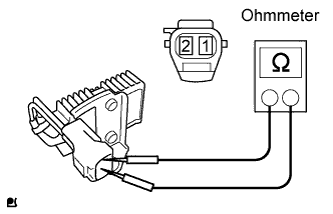
Inspect the fuel pump resistor resistance.
Measure the resistance.
- Standard Resistance:
- 0.941 to 0.999 Ω at 20°C (68°F)
|
NG |
|
|
|
|
| OK |
|
|
|
| 12. CHECK HARNESS AND CONNECTOR (FUEL PUMP RELAY - FUEL PUMP RESISTOR - FUEL PUMP) |
|
Check the harness and connector between the fuel pump relay and fuel pump resistor.
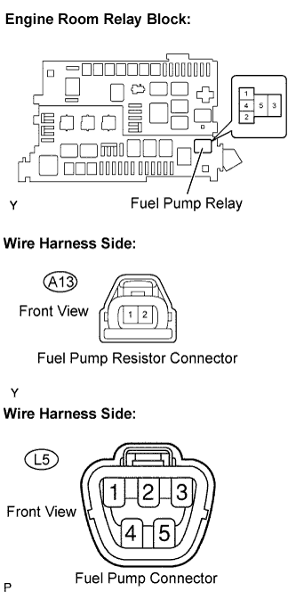
Remove the fuel pump relay from the engine room relay block.
Disconnect the A13 fuel pump resistor connector.
Check the resistance.
- Standard Resistance (Check for open):
Tester Connections
|
Specified Conditions
|
Fuel pump relay (5) - Fuel pump resistor (A13-1)
|
Below 1 Ω
|
- Standard Resistance (Check for short):
Tester Connections
|
Specified Conditions
|
Fuel pump relay (5) or Fuel pump resistor (A13-1) - Body ground
|
10 kΩ or higher
|
Reinstall the fuel pump relay.
Reconnect the fuel pump resistor connector.
Check the harness and connector between the fuel pump resistor and fuel pump.
Disconnect the A13 fuel pump resistor connector.
Disconnect the L5 fuel pump connector.
Check the resistance.
- Standard Resistance (Check for open):
Tester Connections
|
Specified Conditions
|
Fuel pump resistor (A13-2) - Fuel pump (L5-4)
|
Below 1 Ω
|
- Standard Resistance (Check for short):
Tester Connections
|
Specified Conditions
|
Fuel pump resistor (A13-2) or Fuel pump (L5-4) - Body ground
|
10 kΩ or higher
|
Reconnect the fuel pump resistor connector.
Reconnect the fuel pump connector.
|
NG |
|
|
| REPAIR OR REPLACE HARNESS OR CONNECTOR |
|
|
| OK |
|
|
|
| PROCEED TO NEXT CIRCUIT INSPECTION SHOWN IN PROBLEM SYMPTOMS TABLE (Click here)
|
|