C1246/46 Master Cylinder Pressure Sensor Malfunction
Diagnostic trouble codes · Vehicles built Jul 2007 – Oct 2010
Also covers:
- C1281/81 Master Cylinder Pressure Sensor Output Malfunction (Test Mode DTC)
DESCRIPTION
The master cylinder pressure sensor is connected to the skid control ECU in the master cylinder solenoid.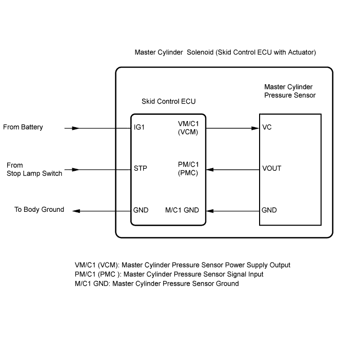

| DTC No. |
DTC Detecting Conditions |
Trouble Areas |
| C1246/46 |
When any of following conditions detected: 1. Both of following conditions continue for at least 30 seconds.
3. Both of following conditions continue for at least 5 seconds.
|
|
| C1281/81 |
Detected only during test mode |
|
INSPECTION PROCEDURE
- NOTICE:
- When replacing the master cylinder solenoid, perform zero point calibration (Click here).
| 1. READ VALUE USING DATA LIST (MASTER CYLINDER PRESSURE SENSOR) |

Connect the intelligent tester to the DLC3.
Start the engine.
Turn the tester on.
Select the following menu items: Chassis / ABS/VSC/TRC/ Data List
DATA LIST: ABS/VSC/TRC Tester Display
Measurement Item / Range
Normal Condition
Diagnostic Note
Master Cylinder Sensor1
Master cylinder pressure sensor 1 reading / min.: 0 V, max.: 5 V
- When brake pedal released: 0.3 to 0.9 V
- When stop lights turned on: 0.3 to 0.9 V
Reading increases when brake pedal depressed
- When brake pedal released: 0.3 to 0.9 V
Check that the master cylinder pressure value of the master cylinder pressure sensor displayed on the intelligent tester changes when the brake pedal is depressed.
- Result:
Result
Proceed to
Master cylinder pressure sensor value normal
A
Master cylinder pressure sensor value changes but not normal
B
Master cylinder pressure sensor value does not change
C
|
|
||||
|
|
||||


| A | |
 |
| 2. RECONFIRM DTC |
Clear the DTCs (Click here).
Check if the same DTC is detected (Click here).
- Result:
Result
Proceed to
DTC output
A
DTC not output
B
|
|
||||
| A | ||
 |
||
| ||
| 3. CHECK BRAKE PEDAL HEIGHT |
Check the brake pedal height.
Check the stop light switch installation.
- OK:
- The brake pedal and stop light switch are normal.
|
|
||||
| OK | |
|
| 4. INSPECT SKID CONTROL ECU TERMINAL VOLTAGE (STP TERMINAL) |
Disconnect the skid control ECU connector.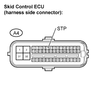
Measure the voltage.
- Standard voltage:
Tester Connection
Condition
Specified Condition
A4-7 (STP) - Body ground
Stop light switch ON
(Brake pedal depressed)
8 to 14 V
A4-7 (STP) - Body ground
Stop light switch OFF
(Brake pedal released)
Below 1.5 V
|
|
||||
| OK | |
|
| 5. RECONFIRM DTC |
Clear the DTC (Click here).
Check if the same DTC is detected (Click here).
- Result:
Result
Proceed to
DTC output
A
DTC not output
B
|
|
||||
| A | ||
|
||
| ||