C1242/42 IG2 Power Source Circuit
Diagnostic trouble codes · Vehicles built Jul 2007 – Oct 2010
DESCRIPTION
If there is a problem with the master cylinder solenoid (skid control ECU) power supply circuit, the skid control ECU outputs the DTC and prohibits operation under the fail-safe function.If the voltage supplied to terminal IG2 is not within the DTC detection threshold due to malfunctions in parts such as the battery and generator circuit, this DTC is stored.
| DTC No. |
DTC Detecting Conditions |
Trouble Areas |
| C1242/42 |
Vehicle speed 3 km/h (2 mph) or more and voltage of skid control ECU terminal IG2 remains at below 6.5 for more than 7 seconds. |
|
WIRING DIAGRAM
Click here.INSPECTION PROCEDURE
- NOTICE:
- When replacing the master cylinder solenoid, perform zero point calibration (Click here).
| 1. CHECK BATTERY VOLTAGE |

Check the battery voltage.
- Standard voltage:
- 11 to 14 V
|
|
||||

| OK | |
 |
| 2. CHECK SKID CONTROL ECU TERMINAL VOLTAGE (IG2) |
Disconnect the skid control ECU A5 connector.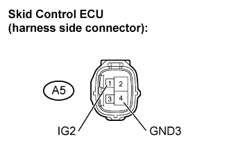

Measure the voltage.
- Standard voltage:
Tester Connection
Specified Condition
A5-1 (IG2) - A5-4 (GND3)
11 to 14 V
|
|
||||
| OK | |
|
| 3. INSPECT FUSE (IGN) |
Remove the IGN fuse from the driver side J/B.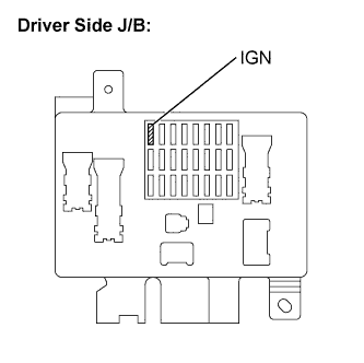
Measure the resistance.
- Standard resistance:
- Below 1 Ω
|
|
||||
| OK | |
|
| 4. CHECK HARNESS AND CONNECTOR (GND TERMINAL CONTINUITY) |
Confirm that the skid control ECU connector and speed sensor connector are properly connected.
Disconnect the skid control ECU connectors.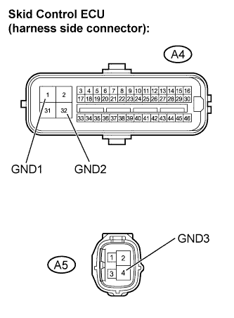
Inspect both the connector case and the terminal for deformation and corrosion.
- OK:
- No deformation or corrosion.
Measure the resistance.
- Standard resistance:
Tester Connection
Specified Condition
A4-1 (GND1) - Body ground
Below 1 Ω
A4-32 (GND2) - Body ground
Below 1 Ω
A5-4 (GND3) - Body ground
Below 1 Ω
|
|
||||
| OK | |
|
| 5. RECONFIRM DTC |
Clear the DTC (Click here).
Drive the vehicle at a speed of 3 km/h (2 mph) or more for 7 seconds or more.
Check if the same DTC is output (Click here).
|
|
||||
| A | ||
 |
||
| ||