When replacing the injectors (including shuffling the injectors between the cylinders), common rail or cylinder head, it is necessary to replace the injection pipes with new ones.
When replacing the fuel supply pump, common rail, cylinder block, cylinder head, cylinder head gasket or timing gear case, it is necessary to replace the fuel inlet pipe with a new one.
1.
DISCHARGE REFRIGERANT FROM REFRIGERATION SYSTEM (w/ Air Conditioning System)
Start up the engine.
Turn the A/C switch on.
Operate the cooler compressor at an engine rpm of approximately 1,000 for 5 to 6 minutes to circulate the refrigerant and collect compressor oil remaining in each component into the cooler compressor as much as possible.
Do not remove the radiator reservoir cap sub-assembly while the engine and radiator are still hot. Pressurized, hot engine coolant and steam may be released and cause serious burns.
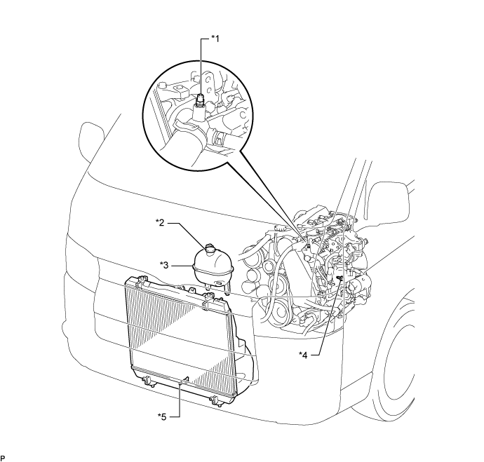
Loosen the radiator drain cock plug.
Text in Illustration
*1
Bleeder Plug
*2
Radiator Reservoir Cap Sub-assembly
*3
Radiator Reservoir Assembly
*4
Cylinder Block Drain Cock Plug
*5
Radiator Drain Cock Plug
-
-
Remove the radiator reservoir cap sub-assembly.
Loosen the cylinder block drain cock plug (on the engine oil cooler cover), and drain the engine coolant.
Tighten the radiator drain cock plug.
Tighten the cylinder block drain cock plug (on the engine oil cooler cover).
Torque:
8.0 N*m{
82 kgf*cm
, 71 in.*lbf
}
3.
DRAIN ENGINE OIL
Remove the oil filler cap.
Remove the oil pan drain plug and gasket, and then drain the engine oil into a container.
Remove the No. 1 intake manifold insulator from the intake manifold.
16.
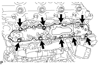
REMOVE INTAKE MANIFOLD (w/ DPF)
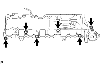
Remove the 7 bolts, 2 nuts and intake manifold.
Remove the gasket.
17.
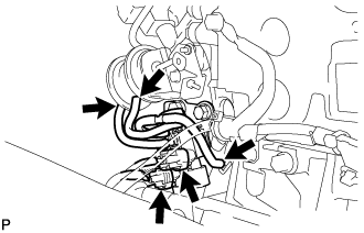
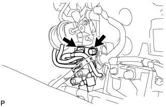
REMOVE VACUUM SWITCHING VALVE SET (w/ DPF)
Remove the 2 connectors and 3 vacuum hoses.
Remove the 2 bolts and vacuum control valve set.
18.
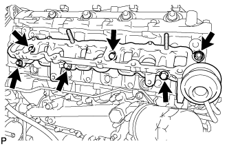
REMOVE SWIRL CONTROL VALVE ASSEMBLY (w/ DPF)
Remove the 4 bolts, 2 nuts and swirl control valve.
Remove the gasket.
19.
REMOVE INTAKE MANIFOLD (w/o DPF)
Remove the 4 bolts, 2 nuts and intake manifold.
Remove the gasket.
20.
REMOVE EXHAUST MANIFOLD
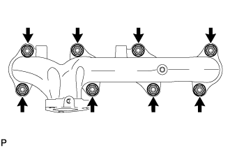
Remove the 8 nuts, 8 plate washers, 8 collars and exhaust manifold.
21.
REMOVE CYLINDER HEAD SUB-ASSEMBLY
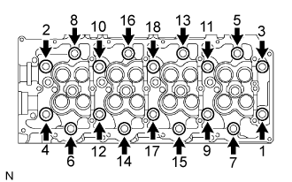
Uniformly loosen the 18 cylinder head bolts in several passes in the sequence shown in the illustration. Then remove the 18 cylinder head bolts and 18 washers.
NOTICE:
Head warpage or cracking could result from removing the bolts in an incorrect order.
Lift the cylinder head from the dowels on the cylinder block and place the cylinder head on wooden blocks on a workbench.
NOTICE:
Be careful not to damage the contact surfaces of the cylinder head or cylinder block.
HINT:
If the cylinder head is difficult to lift, use a screwdriver to pry between the cylinder head and block.