1GD-FTV COOLING WATER PUMP INSTALLATION
PROCEDURE

 16100
1.INSTALL ENGINE WATER PUMP ASSEMBLY
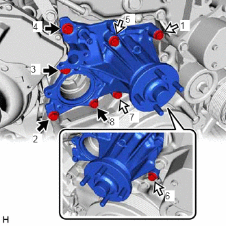

|
Bolt A |

|
Bolt B |
Temporarily install a new water pump gasket and the engine water pump assembly with the 8 bolts.
- Standard Length:
Item Length Bolt A 45 mm (1.77 in.) Bolt B 65 mm (2.56 in.)
Tighten the 8 bolts in the order shown in the illustration.
- Torque:
- 25 N*m (255 kgf*cm, 18 ft.*lbf)
16284
2.CONNECT NO. 1 TURBO WATER HOSE
Connect the No. 1 turbo water hose to the engine water pump assembly, and slide the clip to secure the hose.
- NOTICE:
- ·
Make sure the No. 1 turbo water hose is securely inserted to the stopper.
·Install so that the No. 1 turbo water hose paint mark is aligned with the protrusion of the engine water pump assembly.
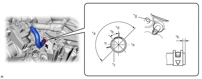
| *a | 180° | *b | 45° |
| *c | Paint Mark | *d | Upper Side |
| *e | LH Side | *f | RH Side |
| *g | Protrusion of the Engine Water Pump Assembly | *h | 0 to 4 mm (0 to 0.157 in.) |
16268
3.CONNECT NO. 1 WATER BY-PASS PIPE
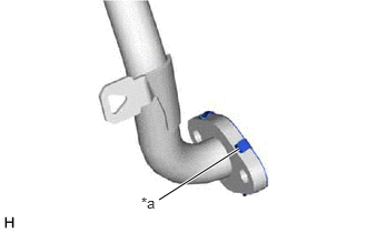
| *a | Claw |
Install a new gasket to the No. 1 water by-pass pipe as shown in the illustration.
- HINT:
-
Make sure that the claws of the gasket are facing the No. 1 water by-pass pipe.
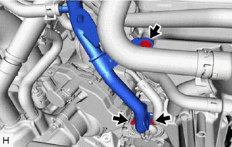
Connect the No. 1 water by-pass pipe to the engine water pump assembly with the 3 bolts.
- Torque:
- 10 N*m (102 kgf*cm, 7 ft.*lbf)
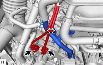
Attach the clamp to connect the wire harness.
Connect the connectors.
16331A
4.INSTALL THERMOSTAT
16321
5.INSTALL WATER INLET
16572D
6.CONNECT NO. 2 RADIATOR HOSE
88704
7.CONNECT SUCTION HOSE SUB-ASSEMBLY (w/ Air Conditioning System, w/o Viscous Heater)
16207
8.CONNECT NO. 2 WATER BY-PASS PIPE SUB-ASSEMBLY
9.INSTALL WATER HOSE SUB-ASSEMBLY (w/ Viscous Heater)
16711
10.INSTALL FAN SHROUD
88359
11.INSTALL VISCOUS HEATER V BELT (w/ Viscous Heater)
16571C
12.INSTALL NO. 1 RADIATOR HOSE
16470
13.INSTALL RADIATOR RESERVE TANK ASSEMBLY
17030
14.INSTALL AIR HOSE ASSEMBLY
44360
15.CONNECT VANE PUMP OIL RESERVOIR ASSEMBLY
17751
16.INSTALL NO. 1 AIR CLEANER INLET
53106B
17.INSTALL RADIATOR COVER SUB-ASSEMBLY
18.ADD ENGINE COOLANT
19.INSPECT FOR COOLANT LEAK
51405A
20.INSTALL NO. 1 ENGINE UNDER COVER SUB-ASSEMBLY
52618
21.INSTALL LOWER FRONT BUMPER ABSORBER
51406A
22.INSTALL NO. 2 ENGINE UNDER COVER SUB-ASSEMBLY (w/ No. 2 Engine Under Cover Sub-assembly)