1GD-FTV COOLING THERMOSTAT INSTALLATION
PROCEDURE

 16331A
1.INSTALL THERMOSTAT
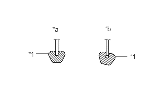
| *1 | Gasket |
| *a | CORRECT |
| *b | INCORRECT |
Install a new gasket to the thermostat.
- NOTICE:
-
When installing the gasket to the thermostat, be careful not to deform the gasket. Make sure that the groove of the gasket is properly installed to the thermostat as shown in the illustration.
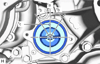
| *a | Upward |
| *b | 30° |
| *c | Jiggle Valve |
Insert the thermostat into the engine water pump assembly with the jiggle valve facing straight upward.
- HINT:
-
The jiggle valve may be set to within 30° on either side of the prescribed position.
16321
2.INSTALL WATER INLET
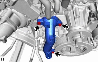
Install the water inlet with the 3 bolts.
- Torque:
- 13 N*m (133 kgf*cm, 10 ft.*lbf)
16572D
3.CONNECT NO. 2 RADIATOR HOSE
w/ Viscous Heater:
Connect the No. 2 radiator hose to the water inlet, and slide the clip to secure the hose.
- NOTICE:
- ·
Make sure the No. 2 radiator hose is securely inserted to the stopper.
·Position the clip so that it is 2 to 5 mm (0.0787 to 0.197 in.) away from the end of the water hose.
·Install so that the No. 2 radiator hose paint mark is aligned with the protrusion of the water inlet.
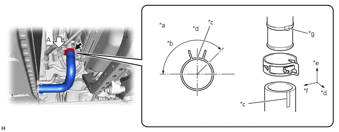
| *a | View A | *b | 135° |
| *c | Paint Mark | *d | Front Side |
| *e | Upper Side | *f | RH Side |
| *g | Protrusion of the Water Inlet | - | - |
w/o Viscous Heater:
Connect the No. 2 radiator hose to the water inlet, and slide the clip to secure the hose.
- NOTICE:
- ·
Make sure the No. 2 radiator hose is securely inserted to the stopper.
·Position the clip so that it is 2 to 5 mm (0.0787 to 0.197 in.) away from the end of the water hose.
·Install so that the No. 2 radiator hose paint mark is aligned with the protrusion of the water inlet.
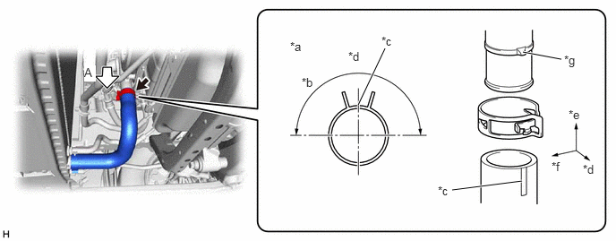
| *a | View A | *b | 180° |
| *c | Paint Mark | *d | Front Side |
| *e | Upper Side | *f | RH Side |
| *g | Protrusion of the Water Inlet | - | - |
88704
4.CONNECT SUCTION HOSE SUB-ASSEMBLY (w/ Air Conditioning System, w/o Viscous Heater)
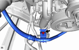
Connect the suction hose sub-assembly to the water inlet with the bolt.
- Torque:
- 9.8 N*m (100 kgf*cm, 87 in.*lbf)
16207
5.CONNECT NO. 2 WATER BY-PASS PIPE SUB-ASSEMBLY
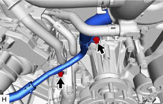
Connect the No. 2 water by-pass pipe sub-assembly to the engine water pump assembly and water inlet with the 2 bolts.
- Torque:
- 10 N*m (102 kgf*cm, 7 ft.*lbf)
6.INSTALL WATER HOSE SUB-ASSEMBLY (w/ Viscous Heater)
16711
7.INSTALL FAN SHROUD
16515A
8.CONNECT INTERCOOLER COOLING WATER PIPE ASSEMBLY (for Water Cooled Type Intercooler)
88359
9.INSTALL VISCOUS HEATER V BELT (w/ Viscous Heater)
161B0
10.INSTALL ELECTRIC WATER PUMP ASSEMBLY (for Water Cooled Type Intercooler)
165A0
11.INSTALL NO. 1 INTERCOOLER COOLING WATER HOSE ASSEMBLY (for Water Cooled Type Intercooler)
16552C
12.INSTALL NO. 2 INTERCOOLER COOLING WATER HOSE (for Water Cooled Type Intercooler)
16571C
13.INSTALL NO. 1 RADIATOR HOSE
16470
14.INSTALL RADIATOR RESERVE TANK ASSEMBLY
16640
15.INSTALL INTERCOOLER RESERVE TANK ASSEMBLY (for Water Cooled Type Intercooler)
17030
16.INSTALL AIR HOSE ASSEMBLY (for Air Cooled Type Intercooler)
44360
17.CONNECT VANE PUMP OIL RESERVOIR ASSEMBLY
17751
18.INSTALL NO. 1 AIR CLEANER INLET
53106B
19.INSTALL RADIATOR COVER SUB-ASSEMBLY
for Wagon:
Click hereVehicle Exterior>EXTERIOR PANELS / TRIM>RADIATOR GRILLE (for Wagon)>INSTALLATION
except Wagon:
Click hereVehicle Exterior>EXTERIOR PANELS / TRIM>RADIATOR GRILLE (except Wagon)>INSTALLATION
12601B
20.INSTALL NO. 1 ENGINE COVER SUB-ASSEMBLY (for Water Cooled Type Intercooler)
21.ADD ENGINE COOLANT (for Water Cooled Type Intercooler)
22.ADD ENGINE COOLANT
23.INSPECT FOR COOLANT LEAK (for Water Cooled Type Intercooler)
24.INSPECT FOR COOLANT LEAK
51405A
25.INSTALL NO. 1 ENGINE UNDER COVER SUB-ASSEMBLY
52618
26.INSTALL LOWER FRONT BUMPER ABSORBER
51406A
27.INSTALL NO. 2 ENGINE UNDER COVER SUB-ASSEMBLY (w/ No. 2 Engine Under Cover Sub-assembly)