 |
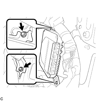
Install the skid control ECU with the 2 bolts.
- Torque:
- 15 N*m{ 153 kgf*cm , 11 in.*lbf }
SKID CONTROL ECU > INSTALLATION |
| 1. INSTALL SKID CONTROL ECU |
|
Install the skid control ECU with the 2 bolts.
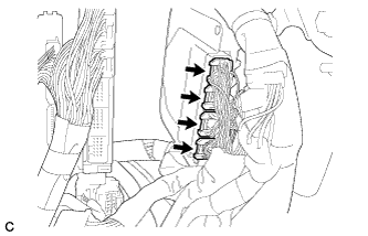 |
Connect the 4 connectors to the skid control ECU.
| 2. INSTALL TIRE PRESSURE MONITOR ECU |
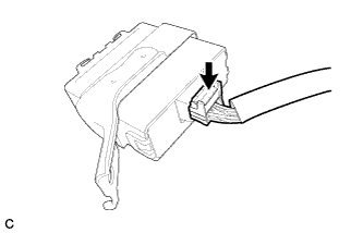 |
Connect the connector to the tire pressure warning ECU.
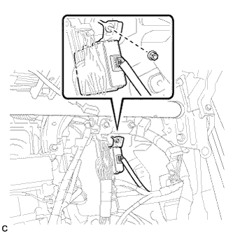 |
Install the tire pressure warning ECU with the nut.
| 3. CONNECT WIRE HARNESS |
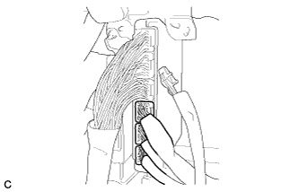 |
Connect the 3 connectors to the hybrid vehicle control ECU.
| 4. INSTALL LOWER INSTRUMENT PANEL SUBASSEMBLY |
Connect each connector and clamp.
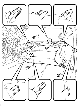 |
Engage the 4 claws and 3 clips.
Install the lower instrument panel sub-assembly with the 2 bolts <B> and 3 screws <E>.
| 5. INSTALL NO. 2 INSTRUMENT PANEL UNDER COVER SUB-ASSEMBLY |
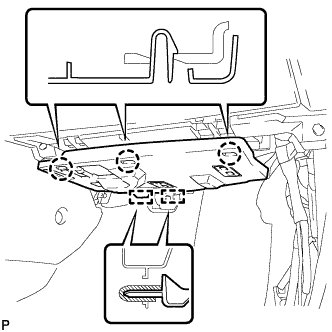 |
Engage the 2 guides.
Engage the 3 claws and install the No. 2 instrument panel under cover sub-assembly.
| 6. INSTALL COWL SIDE TRIM SUB-ASSEMBLY RH |
| 7. INSTALL FRONT DOOR SCUFF PLATE RH |
| 8. INSTALL SERVICE PLUG GRIP |
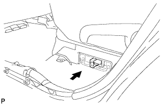 |
Wear insulated gloves, then insert the service plug.
Push down on the grip to lock.
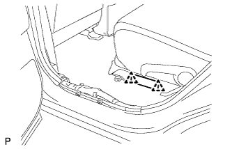 |
Close the reclining hinge cover.
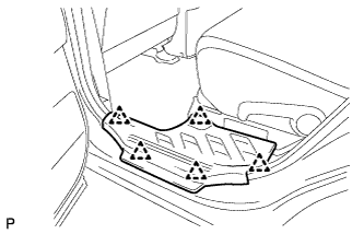 |
Close the rear door scuff plate LH.
| 9. CONNECT CABLE TO NEGATIVE BATTERY TERMINAL |
| 10. INSPECT TIRE PRESSURE WARNING SYSTEM |
| 11. CHECK AND CLEAR DTC |
Check and clear the DTCs (Click here).
| 12. PERFORM LINEAR VALVE OFFSET LEARNING |
When the skid control ECU is replaced, perform linear valve offset learning (Click here).
| 13. PERFORM YAW RATE SENSOR ZERO POINT CALIBRATION |
Perform yaw rate sensor zero point calibration (Click here).
| 14. PERFORM TEST MODE INSPECTION |
Perform test mode inspection (Click here).