PARKING BRAKE PARKING BRAKE PEDAL(for LHD) INSTALLATION
PROCEDURE

 46200
1.INSTALL PARKING BRAKE CONTROL PEDAL ASSEMBLY
Install the parking brake control pedal assembly to the body with the 3 nuts.
- Torque:
- 21 N*m (214 kgf*cm, 15 ft.*lbf)
Connect the parking brake switch connector.
Insert the No. 1 parking brake cable assembly toward the outside of the cabin.
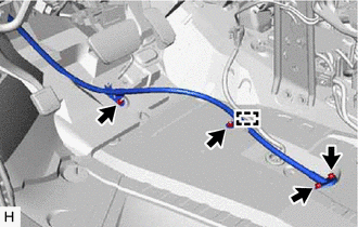
Engage the clamp.
Install the No. 1 parking brake cable assembly to the body with the 2 bolts and 2 nuts.
- Torque:
- Bolt : 8.5 N*m (87 kgf*cm, 75 in.*lbf)
- Nut : 6.0 N*m (61 kgf*cm, 53 in.*lbf)
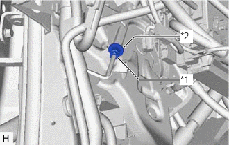
| *1 | Lock Nut |
| *2 | No. 1 Wire Adjusting Nut |
Temporarily install the lock nut.
- HINT:
-
After adjusting parking brake pedal travel, tighten the lock nut.
2.INSTALL WIRE HARNESS CLAMP BRACKET
3.INSTALL INSTRUMENT PANEL JUNCTION BLOCK ASSEMBLY WITH MAIN BODY ECU
46341
4.INSTALL PARKING BRAKE EQUALIZER
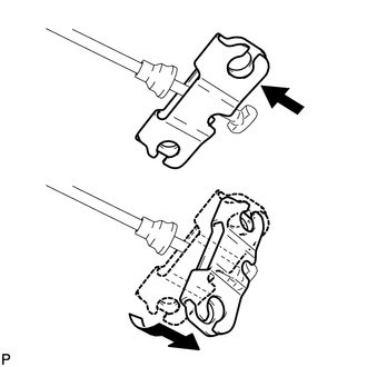
Install the parking brake equalizer to the No. 1 parking brake cable assembly as shown in the illustration.
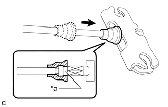
| *a | Groove |
Slide the rubber boot back as shown in the illustration.
- NOTICE:
-
Securely fit the protrusion on the rubber boot into the No. 1 parking brake cable assembly groove.
46430
5.CONNECT NO. 3 PARKING BRAKE CABLE ASSEMBLY
Connect the No. 3 parking brake cable assembly to the parking brake equalizer.
46420
6.CONNECT NO. 2 PARKING BRAKE CABLE ASSEMBLY
- HINT:
-
Perform the same procedure as for the No. 3 parking brake cable assembly.
7.INSPECT PARKING BRAKE PEDAL TRAVEL
8.ADJUST PARKING BRAKE PEDAL TRAVEL
58730
9.INSTALL REAR ENGINE SERVICE COVER ASSEMBLY
Install the rear engine service cover assembly to the body with the 2 bolts.
58167A
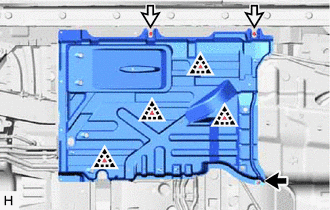
10.INSTALL FRONT CENTER FLOOR COVER

|
Nut |

|
Screw |
Engage the 4 clips to install the front center floor cover.
Install the nut and 2 screws.
58166
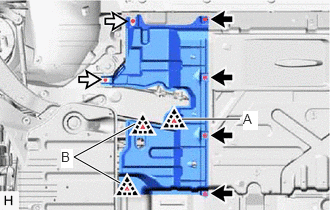
11.INSTALL FRONT FLOOR COVER LH
|
|
Bolt |
|
|
Screw |
Engage the 2 clips (B) to install the front floor cover LH.
Install the 4 bolts, 2 screws and clip (A).
58563Q
12.INSTALL FRONT NO. 3 FLOOR SILENCER
Install the front No. 3 floor silencer to the original position.
58191B
13.INSTALL FRONT FLOOR FOOTREST
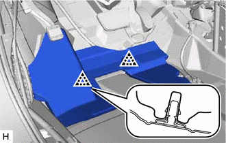
Engage the 2 clips to install the front floor footrest.
87212
14.INSTALL REAR NO. 1 AIR DUCT
87213
15.INSTALL REAR NO. 2 AIR DUCT
58816B
16.INSTALL CONSOLE BOX INSERT
58510D
17.INSTALL FRONT FLOOR CARPET ASSEMBLY
Engage the 3 floor carpet hooks to install the front floor carpet assembly.
73220
18.CONNECT FRONT SEAT OUTER BELT ASSEMBLY LH
62414A
19.INSTALL LOWER CENTER PILLAR GARNISH LH
20.INSTALL REAR DOOR OPENING TRIM WEATHERSTRIP LH
67918A
21.INSTALL REAR DOOR SCUFF PLATE LH
72138M
22.INSTALL REAR OUTER SEAT TRACK BRACKET COVER LH
23.INSTALL FRONT DOOR OPENING TRIM WEATHERSTRIP LH
58810J
24.INSTALL CONSOLE BOX ASSEMBLY
73900
25.INSTALL LOWER NO. 1 INSTRUMENT PANEL AIRBAG ASSEMBLY
26.INSTALL FRONT SEAT ASSEMBLY LH
for Manual Seat: Click hereVehicle Interior>SEAT>FRONT SEAT ASSEMBLY(for Manual Seat)>INSTALLATION
for Power Seat: Click hereVehicle Interior>SEAT>FRONT SEAT ASSEMBLY(for Power Seat)>INSTALLATION
27.INSPECT BRAKE WARNING LIGHT