BRAKE SYSTEM (OTHER) BRAKE BOOSTER(for RHD) REMOVAL
CAUTION / NOTICE / HINT
- NOTICE:
-
Make sure to release vacuum from the brake booster assembly before removing the brake master cylinder sub-assembly from the brake booster assembly.
PROCEDURE

 1. PRECAUTION
- NOTICE:
-
After turning the ignition switch off, waiting time may be required before disconnecting the cable from the negative (-) battery terminal. Therefore, make sure to read the disconnecting the cable from the negative (-) battery terminal notices before proceeding with work.
-
Click hereGeneral>INTRODUCTION>REPAIR INSTRUCTION>PRECAUTION
2. RECOVER REFRIGERANT FROM REFRIGERATION SYSTEM
23100X
3.REMOVE FUEL PUMP ASSEMBLY
4.REMOVE BRAKE MASTER CYLINDER SUB-ASSEMBLY WITH WAY
82111
5.SEPARATE ENGINE ROOM MAIN WIRE
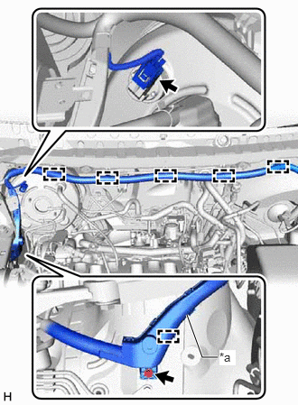
| *a | Wire Harness Protector |
Disconnect the connector from the vacuum warning switch assembly.
Remove the bolt and disengage the clamp to separate the wire harness protector.
Disengage the 5 clamps to separate the engine room main wire.
47220D
6.REMOVE BRAKE MASTER CYLINDER RESERVOIR ASSEMBLY
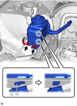
| *1 | Brake Master Cylinder Reservoir Assembly |
| *2 | Reservoir Bracket |
Disconnect the reservoir level switch connector and remove the bolt from the brake master cylinder reservoir assembly.
Move the brake master cylinder reservoir assembly as shown in the illustration to disengage the 2 claws, and remove it.
47233
7.REMOVE RESERVOIR BRACKET
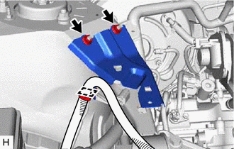
Disengage the clamp to separate the engine room main wire.
Remove the 2 nuts and reservoir bracket.
44773F
8.DISCONNECT UNION TO CHECK VALVE HOSE
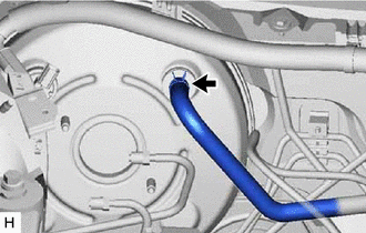
Slide the clip and disconnect the union to check valve hose from the brake booster assembly.
12327A
9.REMOVE NO. 2 ENGINE MOUNTING STAY RH
12313
10.REMOVE ENGINE MOVING CONTROL ROD BRACKET
88704
11.SEPARATE SUCTION HOSE SUB-ASSEMBLY
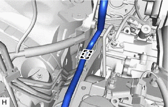
Disengage the clamp to separate the suction hose sub-assembly.
- NOTICE:
- ·
Do not deform the refrigerant lines.
·Do not damage the clamp.
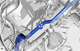
Disengage the clamp to separate the suction hose sub-assembly from the brake actuator assembly.
- NOTICE:
- ·
Do not deform the refrigerant lines.
·Do not damage the clamp.
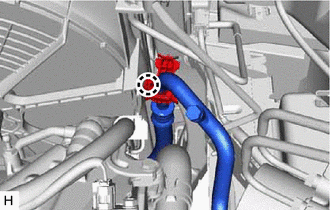
Disengage the claw to separate the suction hose sub-assembly.
- NOTICE:
- ·
Do not deform the refrigerant lines.
·Do not damage the clamp.
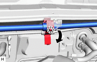
Disengage the claw to release the piping clamp.
- NOTICE:
-
Do not damage the clamp.
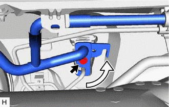
Remove the bolt and rotate the hook connector.
Disconnect the suction hose sub-assembly from the air conditioning unit assembly.
Remove the O-ring from the suction hose sub-assembly.
- NOTICE:
-
Seal the openings of the disconnected parts using vinyl tape to prevent entry of moisture and foreign matter.
Separate the suction hose sub-assembly from the vehicle body.
- NOTICE:
- ·
Do not deform the refrigerant lines.
·Do not damage the clamp.
12.SEPARATE AIR CONDITIONER TUBE AND ACCESSORY ASSEMBLY
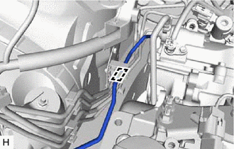
Disengage the clamp to separate the air conditioner tube and accessory assembly from the piping clamp.
- NOTICE:
- ·
Do not deform the refrigerant lines.
·Do not damage the clamp.
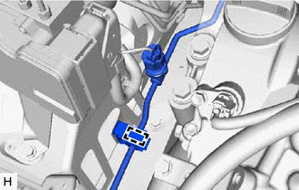
Disengage the clamp to separate the air conditioner tube and accessory assembly from the brake actuator assembly.
- NOTICE:
- ·
Do not deform the refrigerant lines.
·Do not damage the clamp.
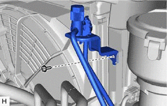
Remove the bolt and separate the air conditioner tube and accessory assembly.
- NOTICE:
-
Do not deform the refrigerant lines.
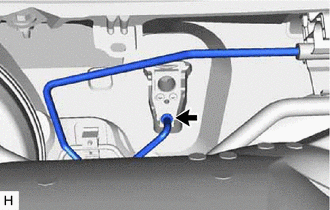
Disconnect the air conditioner tube and accessory assembly from the air conditioning unit assembly.
Remove the O-ring from the air conditioner tube and accessory assembly.
- NOTICE:
-
Seal the openings of the disconnected parts using vinyl tape to prevent entry of moisture and foreign matter.
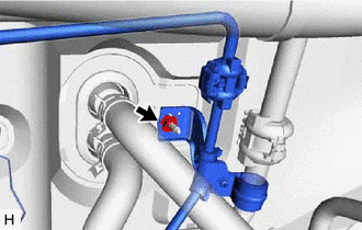
Remove the nut and separate the air conditioner tube and accessory assembly from the vehicle body.
- NOTICE:
-
Do not deform the refrigerant lines.
88704
13.DISCONNECT SUCTION HOSE SUB-ASSEMBLY
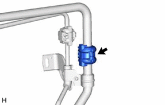
Remove the piping clamp.
Click hereVehicle Interior>HEATING / AIR CONDITIONING>REFRIGERANT LINE>REMOVAL
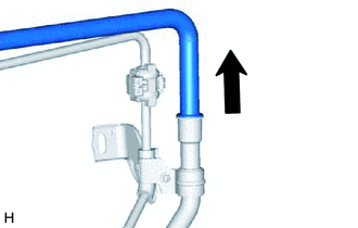
Disconnect the suction hose sub-assembly from the No. 1 air conditioning accessory assembly.
- NOTICE:
-
Do not deform the refrigerant lines.
Remove the 2 O-rings from the suction hose sub-assembly.
- NOTICE:
-
Seal the openings of the disconnected parts using vinyl tape to prevent entry of moisture and foreign matter.
14.SEPARATE BRAKE LINE
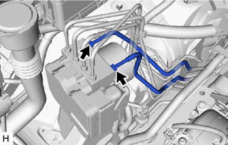
Using a union nut wrench, disconnect the front No. 6 brake tube and front No. 7 brake tube from the brake actuator assembly.
- NOTICE:
- ·
Do not kink or damage the brake lines.
·Do not allow any foreign matter such as dirt or dust to enter the brake line from the connecting parts.
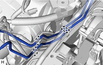
Disengage the 3 clamps and remove the front No. 6 brake tube and front No. 7 brake tube.
- NOTICE:
- ·
Do not damage the 3 clamps.
·Do not kink or damage the brake lines.
12262
15.REMOVE NO. 2 VENTILATION HOSE
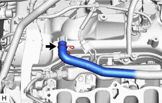
Slide the clip and disconnect the No. 2 ventilation hose to remove it from the cylinder head cover sub-assembly.
82121
16.SEPARATE ENGINE WIRE
Disengage the 4 clamps and disconnect the 8 connectors.
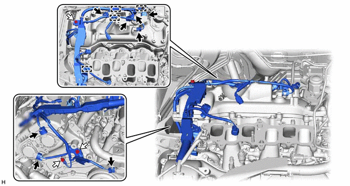

|
Connector | 
|
Bolt |
Remove the 3 bolts to separate the engine wire.
19500
17.REMOVE IGNITION COIL ASSEMBLY
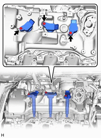
Remove the 3 bolts and 3 ignition coil assemblies.
11401Q
18.REMOVE VVT SENSOR
for Intake Side of Bank 1: Click hereEngine / Hybrid System>2GR-FKS (ENGINE CONTROL)>CAMSHAFT POSITION SENSOR>REMOVAL
11401M
19.REMOVE VVT SENSOR
for Exhaust Side of Bank 1: Click hereEngine / Hybrid System>2GR-FKS (ENGINE CONTROL)>CAMSHAFT POSITION SENSOR>REMOVAL
11201
20.REMOVE CYLINDER HEAD COVER SUB-ASSEMBLY
47101A
21.REMOVE BRAKE PEDAL RETURN SPRING
22.LOOSEN LOCK NUT
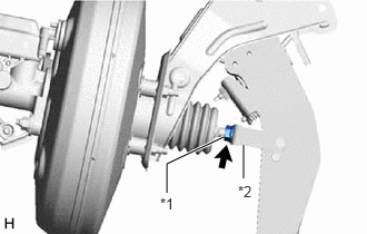
| *1 | Lock Nut |
| *2 | Brake Master Cylinder Push Rod Clevis |
Loosen the lock nut of the brake master cylinder push rod clevis.
47264A
23.REMOVE PUSH ROD PIN
44610
24.REMOVE BRAKE BOOSTER ASSEMBLY
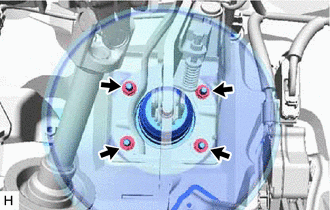
Remove the 4 nuts and push the brake booster assembly toward the engine compartment.
Remove the brake master cylinder push rod clevis and lock nut from the brake booster assembly.
Remove the brake booster assembly from the vehicle body.
44785
25.REMOVE BRAKE BOOSTER GASKET