INSTALLATION
Removal / installation · Vehicles built Aug 2012 – Jul 2013
Versions by build date: Jun 2011 – Jul 2012 Aug 2012 – Jul 2013 from Aug 2013
| 1. INSTALL NO. 3 PARKING BRAKE CABLE ASSEMBLY |

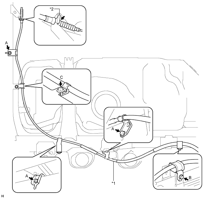

| *1 |
No. 3 Parking Brake Cable |
*2 |
No. 3 Clip |
Install the No. 3 parking brake cable with the 4 bolts and nut.
- Torque:
- for Bolt A, Nut C:
- 26 N*m{ 260 kgf*cm , 19 ft.*lbf }
- for Bolt B:
- 14 N*m{ 143 kgf*cm , 10 ft.*lbf }
Install the No. 3 clip.
Connect the No. 3 parking brake cable to the parking brake shoe lever LH and backing plate LH.
Connect the No. 3 parking brake cable to the backing plate with the 2 bolts.
- Torque:
- 9.0 N*m{ 92 kgf*cm , 80 in.*lbf }
Connect the No. 3 parking brake cable to the parking brake shoe lever (Click here).
| 2. INSTALL NO. 2 PARKING BRAKE CABLE ASSEMBLY |
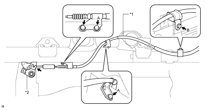
| *1 |
No. 2 Parking Brake Cable |
*2 |
Parking Brake Equalizer |
Install the No. 2 parking brake cable with the 4 bolts.
- Torque:
- for Bolt A:
- 26 N*m{ 260 kgf*cm , 19 ft.*lbf }
- for Bolt B:
- 14 N*m{ 143 kgf*cm , 10 ft.*lbf }
Connect the No. 2 parking brake cable to the parking brake equalizer and apply MP grease to the connecting portion.
Connect the cable to the parking brake shoe lever RH and backing plate RH.
Connect the No. 2 parking brake cable to the backing plate with the 2 bolts.
- Torque:
- 9.0 N*m{ 92 kgf*cm , 80 in.*lbf }
Connect the No. 2 parking brake cable to the parking brake shoe lever (Click here).
- HINT:
- Use the same procedure described for the LH side.
| 3. INSTALL NO. 1 PARKING BRAKE CABLE ASSEMBLY |
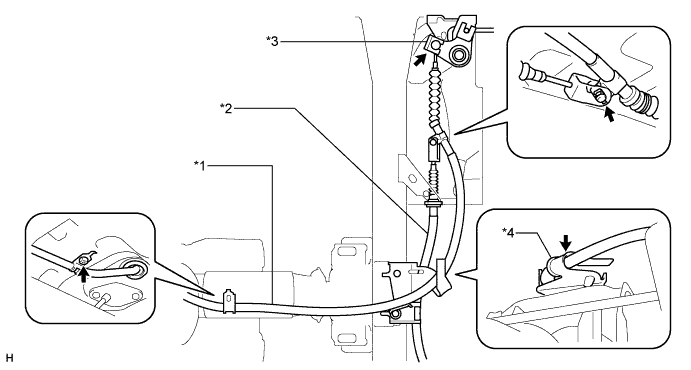
| *1 |
No. 1 Parking Brake Cable |
*2 |
No. 3 Parking Brake Cable |
| *3 |
Parking Brake Equalizer |
*4 |
Cable Support Bracket |
Connect the No. 1 parking brake cable to the parking brake lever (Click here).
Install the No. 1 parking brake cable clamp to the No. 1 parking brake cable.
Install the No. 1 parking brake cable with the bolt.
- Torque:
- 5.0 N*m{ 51 kgf*cm , 44 in.*lbf }
Connect the No. 1 parking brake cable to the parking brake equalizer.
Connect the No. 1 parking brake cable to the No. 3 parking brake cable and apply MP grease to the connecting portion.
Install the pin and No. 1 clip.
Attach the No. 1 parking brake cable to the cable support bracket.
Install the No. 1 heat insulator with the 2 bolts.
- Torque:
- 6.0 N*m{ 61 kgf*cm , 53 in.*lbf }
| 4. CHECK REAR BRAKE DRUM INSTALLATION |
| 5. INSTALL REAR BRAKE DRUM SUB-ASSEMBLY AND NEW GASKET |
Check that each part is installed properly.
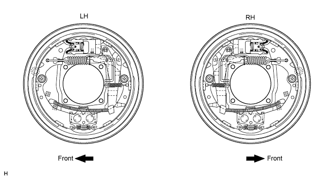
Measure the inside diameter of the drum and diameter of the brake shoes. Check that the difference between the diameters is the correct shoe clearance.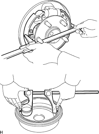
- Standard shoe clearance:
- 0.5 mm (0.0197 in.)
- NOTICE:
- There should be no oil or grease on the contact surfaces of the shoe lining and drum.
| 6. INSTALL REAR WHEEL |
Install the wheel.
- Torque:
- 152 N*m{ 1,550 kgf*cm , 112 ft.*lbf } for steel wheel
- 121 N*m{ 1,234 kgf*cm , 89 ft.*lbf } for aluminum wheel
| 7. ADJUST PARKING BRAKE |
| 8. INSTALL CONSOLE BOX ASSEMBLY |
| 9. CONNECT CABLE TO NEGATIVE BATTERY TERMINAL |
- NOTICE:
- When disconnecting the cable, some systems need to be initialized after the cable is reconnected (Click here).