B279A Theft Deterrent System Communication Line High Fixation
Diagnostic trouble codes · Vehicles built Aug 2012 – Jul 2013
Versions by build date: Jun 2011 – Jul 2012 Aug 2012 – Jul 2013 from Aug 2013
DESCRIPTION
If the communication line (EFIO-IMI) to the transponder key ECU assembly is stuck on HI output, the ECM stores this DTC.| DTC Code |
DTC Detection Condition |
Trouble Area |
DTC Output Confirmation Operation |
| B279A |
The communication line (EFIO-IMI) between the ECM and transponder key ECU assembly is stuck on HI output (1 trip detection logic*). |
|
Turn the ignition switch to ON and wait 6 seconds. |
- *: Only output while a malfunction is present.
| Vehicle Condition when Malfunction Detected |
Fail-safe Operation when Malfunction Detected |
| Engine cannot be started (initial ignition occurs and engine cranks, then ignition stop). |
Engine cannot be started. |
| DTC Code |
Data List and Active Test |
| B279A |
- |
WIRING DIAGRAM
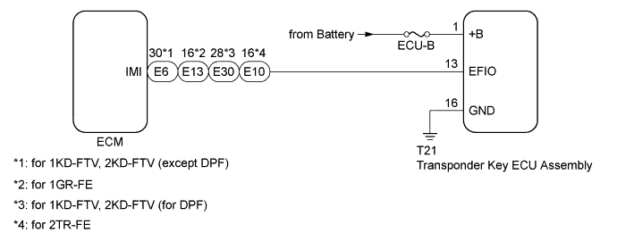

INSPECTION PROCEDURE
- NOTICE:
- When replacing the transponder key ECU assembly or ECM, refer to the Service Bulletin.
- After performing repairs, perform the operation that fulfills the DTC output confirmation operation, and then confirm that no DTCs are output again.
- Inspect the fuses for circuits related to this system before performing the following inspection procedure.
- When replacing the transponder key ECU assembly or ECM, refer to the Service Bulletin.
- HINT:
- After troubleshooting for this DTC, make sure B279A is not present. If present, troubleshoot the blocking system DTCs next.
| 1. CLEAR DTC |

Clear the DTCs (Click here).
| NEXT | |
 |
| 2. CHECK FOR DTC |
Check for DTCs (Click here).
Result Result
Proceed to
No DTC is output
A
DTC B279A and other DTCs are output
B
DTC B279A is output
C
- HINT:
- If any DTCs other than B279A are output, troubleshoot those DTCs first.
|
|
||||
|
|
||||


| A | ||
 |
||
| ||
| 3. CHECK HARNESS AND CONNECTOR (SFI OR ECD COMMUNICATION LINE) |
Disconnect the T21 transponder key ECU assembly connector.
Disconnect the E6*1, E13*2, E30*3 or E10*4 ECM connector.
- *1: for 1KD-FTV, 2KD-FTV (except DPF)
- *2: for 1GR-FE
- *3: for 1KD-FTV, 2KD-FTV (for DPF)
- *4: for 2TR-FE
- *1: for 1KD-FTV, 2KD-FTV (except DPF)
Measure the resistance according to the value(s) in the table below.
- Standard Resistance:
- for 1KD-FTV, 2KD-FTV (except DPF):
Tester Connection
Condition
Specified Condition
T21-13 (EFIO) - E6-30 (IMI)
Always
Below 1 Ω
T21-13 (EFIO) or E6-30 (IMI) - Body ground
Always
10 kΩ or higher
- for 1GR-FE:
Tester Connection
Condition
Specified Condition
T21-13 (EFIO) - E13-16 (IMI)
Always
Below 1 Ω
T21-13 (EFIO) or E13-16 (IMI) - Body ground
Always
10 kΩ or higher
- for 1KD-FTV, 2KD-FTV (for DPF):
Tester Connection
Condition
Specified Condition
T21-13 (EFIO) - E30-28 (IMI)
Always
Below 1 Ω
T21-13 (EFIO) or E30-28 (IMI) - Body ground
Always
10 kΩ or higher
- for 2TR-FE:
Tester Connection
Condition
Specified Condition
T21-13 (EFIO) - E10-16 (IMI)
Always
Below 1 Ω
T21-13 (EFIO) or E10-16 (IMI) - Body ground
Always
10 kΩ or higher
Measure the voltage according to the value(s) in the table below.
- Standard Voltage:
- for 1KD-FTV, 2KD-FTV (except DPF):
Tester Connection
Condition
Specified Condition
T21-13 (EFIO) or E6-30 (IMI) - Body ground
Always
Below 1 V
- for 1GR-FE:
Tester Connection
Condition
Specified Condition
T21-13 (EFIO) or E13-16 (IMI) - Body ground
Always
Below 1 V
- for 1KD-FTV, 2KD-FTV (for DPF):
Tester Connection
Condition
Specified Condition
T21-13 (EFIO) or E30-28 (IMI) - Body ground
Always
Below 1 V
- for 2TR-FE:
Tester Connection
Condition
Specified Condition
T21-13 (EFIO) or E10-16 (IMI) - Body ground
Always
Below 1 V
|
|
||||
| OK | |
|
| 4. CHECK TRANSPONDER KEY ECU ASSEMBLY (TERMINAL EFIO) |
Using an oscilloscope, check the waveform.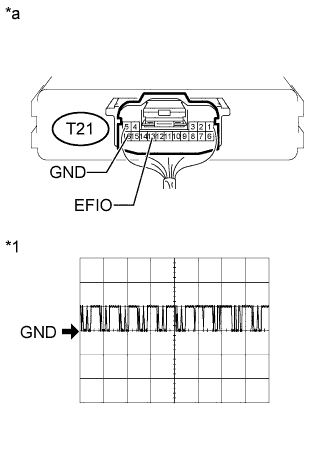
Measurement Condition Item
Content
Tester Connection
T21-13 (EFIO) - T21-16 (GND)
Tool Setting
10V/DIV., 100 ms./DIV.
Condition
Ignition switch ON
- HINT:
- The waveform shown in the illustration is an example for reference only. Noise, chattering, etc. are not shown.
- OK:
- Waveform is output normally (refer to illustration).
| *1 |
Waveform |
| *a |
Component with harness connected (Transponder Key ECU Assembly) |
|
|
||||
| OK | ||
|
||
| ||
| 5. CHECK HARNESS AND CONNECTOR (TRANSPONDER KEY ECU - BATTERY AND BODY GROUND) |
Disconnect the T21 transponder key ECU assembly connector.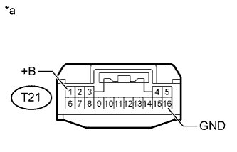
Measure the resistance according to the value(s) in the table below.
- Standard Resistance:
Tester Connection
Condition
Specified Condition
T21-16 (GND) - Body ground
Always
Below 1 Ω
Measure the voltage according to the value(s) in the table below.
- Standard Voltage:
Tester Connection
Condition
Specified Condition
T21-1 (+B) - Body ground
Always
11 to 14 V
| *a |
Front view of wire harness connector (to Transponder Key ECU Assembly) |
|
|
||||
| OK | |
|
| 6. REPLACE ECM |
Temporarily replace the ECM with a new one.
- for 1KD-FTV (except DPF): Click here
- for 1KD-FTV (for DPF): Click here
- for 2KD-FTV (except DPF): Click here
- for 2KD-FTV (for DPF): Click here
- for 1GR-FE: Click here
- for 2TR-FE: Click here
- for 1KD-FTV (except DPF): Click here
| NEXT | |
|
| 7. REGISTER ECU COMMUNICATION ID |
Register the ECU - ECM communication ID (Refer to the Service Bulletin).
| NEXT | |
|
| 8. CLEAR DTC |
Clear the DTCs (Click here).
| NEXT | |
|
| 9. CHECK FOR DTC |
Check for DTCs (Click here).
- OK:
- DTC B279A is not output.
|
|
||||
| OK | ||
|
||
| ||