1KD-FTV ENGINE MECHANICAL ENGINE UNIT(w/o Glow Plug Controller) INSTALLATION
CAUTION / NOTICE / HINT
- NOTICE:
- ·
When replacing the injectors (including shuffling the injectors between the cylinders), common rail or cylinder head, it is necessary to replace the injection pipes with new ones.
·When replacing the fuel supply pump, common rail, cylinder block, cylinder head, cylinder head gasket or timing gear case, it is necessary to replace the fuel inlet pipe with a new one.
·After removing the injection pipes, clean them with a brush and compressed air.
PROCEDURE

 1.INSTALL FRONT NO. 1 ENGINE MOUNTING BRACKET LH
Install the front No. 1 engine mounting bracket with the 4 bolts.
- Torque:
- 68 N*m (693 kgf*cm, 50 ft.*lbf)
2.INSTALL FRONT NO. 1 ENGINE MOUNTING BRACKET RH
Install the front No. 1 engine mounting bracket with the 4 bolts.
- Torque:
- 68 N*m (693 kgf*cm, 50 ft.*lbf)
3.INSTALL ENGINE COOLANT TEMPERATURE SENSOR
4.INSTALL CAMSHAFT POSITION SENSOR
5.INSTALL CRANKSHAFT POSITION SENSOR
6.INSTALL VANE PUMP ASSEMBLY
Install a new O-ring to the vane pump.
Install the vane pump with the 2 nuts.
- Torque:
- 41 N*m (418 kgf*cm, 30 ft.*lbf)
7.INSTALL VACUUM PUMP ASSEMBLY
Install 2 new O-rings to the vacuum pump.
Install the vacuum pump with the 2 nuts.
- Torque:
- 21 N*m (210 kgf*cm, 15 ft.*lbf)
8.INSTALL TIMING GEAR COVER INSULATOR (w/ EGR Cooler)
Install the gear cover insulator with the bolt.
- Torque:
- 13 N*m (133 kgf*cm, 10 ft.*lbf)
9.INSTALL OIL COOLER COVER SUB-ASSEMBLY
10.INSTALL FUEL SUPPLY PUMP ASSEMBLY
11.INSTALL COMMON RAIL ASSEMBLY
12.INSTALL FUEL INLET PIPE SUB-ASSEMBLY
13.INSTALL OIL FILTER SUB-ASSEMBLY
14.INSTALL GLOW PLUG ASSEMBLY
15.INSTALL INTAKE MANIFOLD
16.INSTALL DIESEL THROTTLE BODY ASSEMBLY
17.INSTALL WATER OUTLET
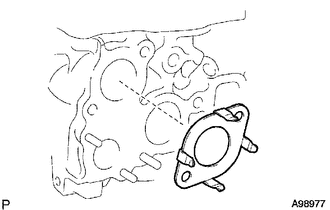
| *1 | Claw |
Install a new gasket to the cylinder head as shown in the illustration.
- HINT:
-
Make sure the claws of the gasket face the water outlet.
Install the water outlet with the 2 bolts.
- Torque:
- 19 N*m (194 kgf*cm, 14 ft.*lbf)
18.INSTALL THERMOSTAT
19.INSTALL WATER INLET
20.INSTALL NO. 1 COMPRESSOR MOUNTING BRACKET (w/ Air Conditioning System)
Install the No. 1 compressor mounting bracket with the 4 bolts.
- Torque:
- 45 N*m (459 kgf*cm, 33 ft.*lbf)
21.INSTALL V-RIBBED BELT TENSIONER ASSEMBLY
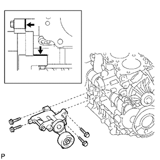
| *1 | Cylinder Block |
| *2 | V-ribbed Belt Tensioner |
Install the V-ribbed belt tensioner with the 4 bolts.
- Torque:
- 21 N*m (214 kgf*cm, 15 ft.*lbf)
- HINT:
-
Firmly press and hold the V-ribbed belt tensioner against the cylinder block to eliminate any gaps in the areas labeled A in the illustration. Then uniformly tighten the 4 bolts.
22.INSTALL GENERATOR BRACKET
Install the generator bracket with the bolt.
- Torque:
- 25 N*m (255 kgf*cm, 18 ft.*lbf)
23.INSTALL GENERATOR ASSEMBLY
24.INSTALL NO. 2 IDLE PULLEY ASSEMBLY
25.INSTALL EXHAUST MANIFOLD WITH TURBOCHARGER
Install a new gasket and the exhaust manifold with turbocharger to the cylinder head with the 8 plate washers, 8 collars and 8 new nuts.
- Torque:
- 40 N*m (408 kgf*cm, 30 ft.*lbf)
26.INSTALL TURBOCHARGER STAY
27.INSTALL TURBINE OUTLET ELBOW
28.INSTALL NO. 1 TURBO WATER HOSE
29.INSTALL NO. 1 EXHAUST MANIFOLD HEAT INSULATOR
30.INSTALL NO. 1 TURBO INSULATOR
31.INSTALL COMPRESSOR INLET ELBOW
32.INSTALL VENTILATION PIPE
33.INSTALL INTERCOOLER SUPPORT BRACKET
Install the intercooler support bracket with the 2 bolts.
- Torque:
- 32 N*m (326 kgf*cm, 24 ft.*lbf)
34.INSTALL NO. 2 INTERCOOLER SUPPORT BRACKET
Install the No. 2 intercooler support bracket with the 2 bolts.
- Torque:
- 32 N*m (326 kgf*cm, 24 ft.*lbf)
35.INSTALL CRANKSHAFT PULLEY
36.INSTALL NO. 1 TIMING BELT IDLER SUB-ASSEMBLY
37.INSTALL TIMING BELT
38.INSTALL NO. 1 TIMING BELT COVER