2KD-FTV ENGINE MECHANICAL ENGINE ASSEMBLY(w/ DPF) INSTALLATION
CAUTION / NOTICE / HINT
- NOTICE:
- ·
When replacing the injectors (including shuffling the injectors between the cylinders), common rail or cylinder head, it is necessary to replace the injection pipes with new ones.
·When replacing the fuel supply pump, common rail, cylinder block, cylinder head, cylinder head gasket or timing gear case, it is necessary to replace the fuel inlet pipe with a new one.
·After removing the injection pipes, clean them with a brush and compressed air.
PROCEDURE

 1.INSTALL FRONT ENGINE MOUNTING INSULATOR
Install the 2 front engine mounting insulators with the 2 nuts.
- Torque:
- 48 N*m (489 kgf*cm, 35 ft.*lbf)
2.INSTALL ENGINE WIRE
Install the engine wire to the engine.
3.INSTALL ENGINE HANGERS
4.REMOVE ENGINE FROM ENGINE STAND
Attach an engine sling device and hang the engine with a chain block.
Remove the engine from the engine stand.
5.INSTALL ENGINE ASSEMBLY
Slowly lower the engine into the engine compartment.
Install the engine with the 4 bolts and 4 nuts.
- Torque:
- 38 N*m (387 kgf*cm, 28 ft.*lbf)
Remove the 2 bolts and 2 engine hangers.
6.INSTALL REAR END PLATE
Install the rear end plate with the bolt.
- Torque:
- 8.0 N*m (82 kgf*cm, 71 in.*lbf)
7.INSTALL FLYWHEEL SUB-ASSEMBLY
Clean the bolts and their holes.
Apply adhesive to 2 or 3 threads at the end of each bolt.
- Adhesive:
Toyota Genuine Adhesive 1324, Three Bond 1324 or equivalent
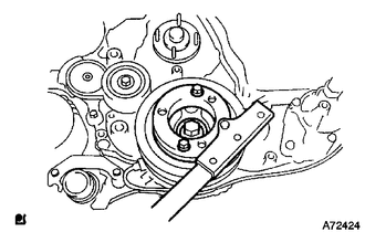
Using SST, hold the crankshaft pulley.
- SST
- 09213-58014
09330-00021
Install the flywheel to the crankshaft.
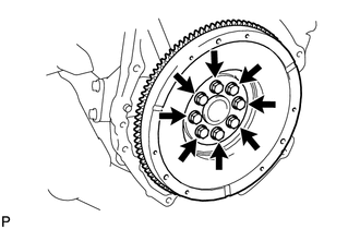
Install and uniformly tighten the 8 bolts in the sequence shown in the illustration.
- Torque:
- 178 N*m (1815 kgf*cm, 131 ft.*lbf)
- NOTICE:
-
Do not start the engine for at least 1 hour after installation.
8.INSTALL CLUTCH DISC ASSEMBLY
9.INSTALL CLUTCH COVER ASSEMBLY
10.INSPECT AND ADJUST CLUTCH COVER ASSEMBLY
11.INSTALL REAR NO. 1 ENGINE MOUNTING INSULATOR
- HINT:
-
Perform this procedure only when replacement of the rear No. 1 engine mounting insulator is necessary.
Install the 4 bolts and rear No. 1 engine mounting insulator.
- Torque:
- 47 N*m (479 kgf*cm, 35 ft.*lbf)
12.INSTALL MANUAL TRANSMISSION ASSEMBLY
13.CONNECT COOLER COMPRESSOR ASSEMBLY (w/ Air Conditioning System)
Connect the cooler compressor with the 4 bolts.
- Torque:
- 25 N*m (250 kgf*cm, 18 ft.*lbf)
14.CONNECT WIRE HARNESS
Connect the 6 ECM connectors.
Connect the 4WD control ECU connector.
Connect the 4 injector driver connectors.
Connect the 4 glow plug controller connectors.
Attach the clamp and connect the wire harness with the 2 nuts.
- Torque:
- 13 N*m (131 kgf*cm, 9 ft.*lbf)
Connect the ground cable with the bolt.
- Torque:
- 30 N*m (306 kgf*cm, 22 ft.*lbf)
Connect the 2 engine room junction block connectors.
Connect the engine room junction block wire with the nut.
- Torque:
- 13 N*m (133 kgf*cm, 10 ft.*lbf)
Install the side engine room relay block cover.
Install the upper relay block cover.
15.INSTALL GLOVE COMPARTMENT DOOR ASSEMBLY
16.CONNECT UNION TO CONNECTOR TUBE HOSE
Connect the union to connector tube hose.
17.CONNECT FUEL HOSE
Connect the 2 fuel hoses.
18.CONNECT PRESSURE FEED TUBE ASSEMBLY
Connect the pressure feed tube.
- Torque:
- 44 N*m (449 kgf*cm, 32 ft.*lbf)
- NOTICE:
-
Use the formula to calculate special torque values for situations where a union nut wrench is combined with a torque wrench (See page General>INTRODUCTION>REPAIR INSTRUCTION>PRECAUTION).
Connect the oil reservoir to pump hose.
19.CONNECT HEATER HOSE
Connect the 2 heater hoses.
20.INSTALL PROPELLER WITH CENTER BEARING SHAFT ASSEMBLY
21.INSTALL FRONT PROPELLER SHAFT ASSEMBLY (for 4WD)
22.INSTALL FRONT EXHAUST PIPE ASSEMBLY
23.INSTALL STARTER ASSEMBLY
for Denso Made: (See page Engine / Hybrid System>2KD-FTV STARTING>STARTER(for DENSO Made)>INSTALLATION)
for Bosch Made: (See page Engine / Hybrid System>2KD-FTV STARTING>STARTER(for BOSCH Made)>INSTALLATION)
24.INSTALL RADIATOR ASSEMBLY
25.INSTALL INTERCOOLER ASSEMBLY WITH INTAKE AIR CONNECTOR
26.INSTALL AIR CLEANER ASSEMBLY
27.INSTALL BATTERY TRAY
28.INSTALL BATTERY
29.INSTALL BATTERY CLAMP SUB-ASSEMBLY
Install the battery clamp with the bolt and nut.
- Torque:
- 5.4 N*m (55 kgf*cm, 48 in.*lbf)
30.ADD POWER STEERING FLUID
31.ADD TRANSMISSION OIL
33.INSTALL HOOD SUB-ASSEMBLY
Install the hood with the 4 bolts.
- Torque:
- 13 N*m (133 kgf*cm, 10 ft.*lbf)
Connect the washer nozzle hose.
Adjust the hood (See page Vehicle Exterior>DOOR / HATCH>HOOD>ADJUSTMENT).
34.CONNECT CABLE TO NEGATIVE BATTERY TERMINAL
- NOTICE:
-
When disconnecting the cable, some systems need to be initialized after the cable is reconnected (See page General>INTRODUCTION>REPAIR INSTRUCTION>INITIALIZATION).
35.BLEED AIR FROM FUEL SYSTEM
36.ADD ENGINE COOLANT
37.BLEED AIR FROM POWER STEERING SYSTEM
38.INSPECT POWER STEERING FLUID LEVEL
39.PERFORM REGISTRATION
Perform registration of the injector compensation codes (See page Engine / Hybrid System>2KD-FTV ENGINE CONTROL>ECD SYSTEM(for DPF)>REGISTRATION).
Perform pilot quantity learning (See page Engine / Hybrid System>2KD-FTV ENGINE CONTROL>ECD SYSTEM(for DPF)>REGISTRATION).
40.INSPECT FOR COOLANT LEAK
41.INSPECT FOR OIL LEAK
42.INSPECT FOR EXHAUST GAS LEAK
43.INSPECT FOR FUEL LEAK
44.CHECK ENGINE IDLE SPEED AND MAXIMUM SPEED
45.INSPECT ENGINE OIL LEVEL
46.INSTALL NO. 2 ENGINE UNDER COVER
- Torque:
- 28 N*m (286 kgf*cm, 21 ft.*lbf)
47.INSTALL NO. 1 ENGINE UNDER COVER
- Torque:
- 28 N*m (286 kgf*cm, 21 ft.*lbf)