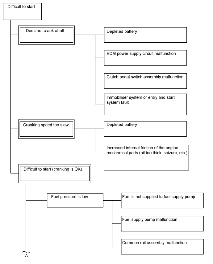
ECD SYSTEM (for i-ART) > Engine Difficult to Start or Stalling |
| Faults and Symptoms of Common Rail Diesel Components |
Engine Control
| Main fault | Decrease in performance (foreign matter is stuck) | |
| Symptoms | Lack of power, black smoke | |
| Data List | MAF | |
| ||
| Symptom and Corresponding Main Fault |
| |
| Data List | MAP | |
| Main fault |
| |
| Symptoms | Lack of power (when vehicle is starting, under heavy load) (Black smoke is not emitted when racing while vehicle is stopped) | |
| Data List | MAP
| |
| Main fault | Blockage | |
| Symptoms | Lack of power (high engine speed, under heavy load) | |
| Main fault | Glow system malfunction | |
| Symptoms | Difficult to start, rough idle, knocking, white smoke (when cold) | |
| Data List | Check the glow plug indicator light | |
| Diagnostic Point | Measure the resistance of the glow plug | |
| Main fault | Battery is depleted | |
| Symptoms | Difficult to start (cannot crank, crank speed is low), horn is quiet | |
| Data List | Battery Voltage When cranking, battery voltage is below 5 V. | |
| Main fault | Damaged, seized up | |
| Symptoms | Cannot crank, crank speed is low, strange noise | |
| Main fault | Loss of compression | |
| Symptoms | Rough idle (lack of power always) | |
| Data List | Engine Speed of Cyl
| |
| Main fault | Starter system malfunction | |
| Symptoms | Difficult to start | |
| Data List | Starter Signal
| |
Diesel Injection
| Main fault | - | |
| Symptoms | Difficult to start, engine stalling, rough idle, lack of power | |
| Data List | Fuel Press, Target Common Rail Pressure, Target Pump SCV Current
| |
| Diagnostic Trouble Code | Even if Fuel Press is below Target Common Rail Pressure, a DTC will not be stored. | |
| Main fault | Blockage | |
| Symptoms | Difficult to start, engine stalling, rough idle, lack of power | |
| Data List | Fuel Press, Target Common Rail Pressure
| |
| Diagnostic Trouble Code | Even if Fuel Press is below Target Common Rail Pressure, a DTC will not be stored. | |
| Main fault | Blockage | |
| Symptoms | Rough idle, lack of power, black smoke, white smoke, knocking | |
| Data List | Injection Feedback Val
| |
| Main fault | Does not completely close | |
| Symptoms | Difficult to start, engine stall, rough idle, lack of power | |
| Main fault | Circuit fault: The injector assembly does not open. | |
| Symptoms | Difficult to start, rough idle, lack of power, black smoke, white smoke, knocking | |
| Data List | Same as injector assembly | |
| Diagnostic Trouble Code | When the injector driver has a fault, some DTCs may be stored. | |
| Main fault | Open circuit, decrease in performance (foreign matter is stuck) | |
| Symptoms | Difficult to start, rough idle, engine stall, lack of power | |
| Data List | Fuel Press, Target Common Rail Pressure
| |
| Diagnostic Trouble Code | When the fuel pressure sensor has a fault, some DTCs may be stored. | |
| Main fault | - | |
| Symptoms | Difficult to start, rough idle (especially when cold) | |
Diesel EGR
| Main fault |
| |
| Symptoms |
| |
| Data List | Actual EGR Valve Pos., Target EGR Position
| |
Diesel Throttle
| Main fault | Stuck, does not move smoothly | |
| Symptoms |
| |
| Data List |
| |
| Data List Related to Starting Trouble |
| Explanation of Symptom |
| Starting Trouble | For good starting it is essential to have:
With problems such as a depleted battery, the crankshaft speed can become low, or if the engine compression is poor due to leakage, the compression pressure will not rise and there will be difficulty starting. When the engine is cold, even if there is compression heat, it will escape from the combustion chamber. For this reason, when the engine is started when it is cold, the glow plugs heat the compressed air. Also, after starting the engine, by charging the glow plugs for a fixed time set according to the engine coolant temperature, diesel knocking and white smoke are prevented. The quantity of fuel injected is determined by the fuel pressure and also the amount of time the injector assembly is open. |
| Trouble Area Chart According to Problem Cause |
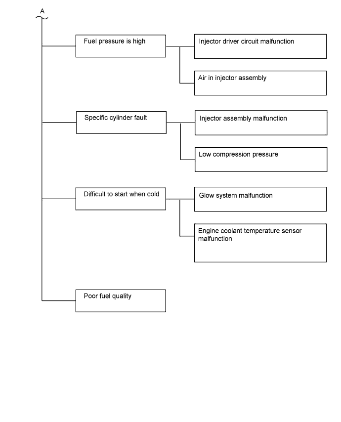
| 1.CHECK ENGINE CRANKING CONDITION |
Check the engine cranking condition.
| Result | Proceed to |
| Cranking is OK. | A |
Low cranking speed.
| B |
| Does not crank at all. | C |
|
| ||||
|
| ||||
| A | |
 |
| 2.READ ALL OUTPUT DTCS |
Connect the GTS to the DLC3.
Turn the ignition switch to ON and turn the GTS on.
Enter the following menus: Utility / All Codes.
| Result | Proceed to |
| No DTC is output | A |
| Engine related DTCs are output | B |
|
| ||||
| A | |
|
| 3.TAKE SNAPSHOT DURING STARTING AND IDLING (PROCEDURE 3) |
Connect the GTS to the DLC3.
Turn the ignition switch to ON and turn the GTS on.
Enter the following menus: Powertrain / Engine / Data List / All Data.
Take a snapshot when idling with no load after the engine is warmed up and when starting trouble is occurring.
| NEXT | |
|
| 4.CHECK SNAPSHOT (FUEL PRESS) |
Check Fuel Press in the snapshot taken in procedure 3 when the engine was started.
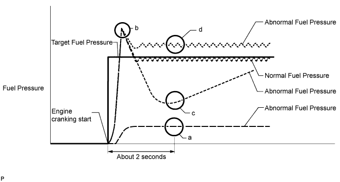
| Result | Proceed to |
| At the point in the illustration labeled "a", Fuel Press is less than 10000 kPa from the value of Fuel Press when cranking started | A |
| At the point in the illustration labeled "c", Fuel Press is below Target Common Rail Pressure by 15000 kPa or more | B |
| Fuel Press increases to a value that is higher than Target Common Rail Pressure immediately after cranking, and, at the point in the illustration labeled "d", Fuel Press is higher than Target Common Rail Pressure | C |
| Except above | D |
|
| ||||
|
| ||||
|
| ||||
| A | |
|
| 5.CHECK IF FUEL IS BEING SUPPLIED TO FUEL SUPPLY PUMP |
Disconnect the inlet hose from the Fuel Supply Pump.
Operate the priming pump and check that fuel is being supplied to the Fuel Supply Pump.
Reconnect the inlet hose.
|
| ||||
| OK | |
|
| 6.CHECK HARNESS AND CONNECTOR (SUCTION CONTROL VALVE - ECM) |
Disconnect the suction control valve connector.
Disconnect the ECM connector.
Measure the resistance according to the value(s) in the table below.
| Tester Connection | Condition | Specified Condition |
| S8-1 - E27-23 (PCV+) | Always | Below 1 Ω |
| S8-2 - E27-12 (PCV-) | Always | Below 1 Ω |
| S8-1 or E27-23 (PCV+) - Body ground | Always | 10 kΩ or higher |
| S8-2 or E27-12 (PCV-) - Body ground | Always | 10 kΩ or higher |
Reconnect the suction control valve connector.
Reconnect the ECM connector.
|
| ||||
| OK | |
|
| 7.REPLACE FUEL SUPPLY PUMP ASSEMBLY (SUCTION CONTROL VALVE) |
Replace the fuel supply pump assembly (Click here).
| NEXT | |
|
| 8.BLEED AIR FROM FUEL SYSTEM |
Bleed the air from the fuel system .
| NEXT | |
|
| 9.PERFORM SUPPLY PUMP INITIALIZATION |
Perform supply pump initialization (Click here).
| NEXT | |
|
| 10.READ VALUE USING GTS (FUEL PRESS) |
Connect the GTS to the DLC3.
Turn the ignition switch to ON and turn the GTS on.
Enter the following menus: Powertrain / Engine / Data List / Fuel Press.
Start the engine.
Read the Fuel Press values while cranking and idling the engine.
| Result | Proceed to |
| The engine cannot be started or the engine can be started but Fuel Press is below 20000 kPa 2 seconds after the starter signal changes from OFF to ON | B |
| Except above | A |
|
| ||||
| B | |
|
| 11.INSPECT INJECTOR ASSEMBLY (INSPECTION FOR VALVE CLOSING PROBLEM) |
Remove the glow plug assembly for all the cylinders (Click here).
Visually check if there is fuel on the glow plugs.
Install the glow plug assembly (Click here).
|
| ||||
| 12.CHECK AND REPAIR OR REPLACE CLOGGED FUEL PIPE (INCLUDING FROZEN FUEL) (FUEL TANK - FUEL SUPPLY PUMP) |
Check and repair or replace the clogged fuel pipe.
| NEXT | |
|
| 13.BLEED AIR FROM FUEL SYSTEM |
Bleed the air from the fuel system .
|
| ||||
| 14.READ VALUE USING GTS (FUEL PRESS) |
Check Fuel Press in the snapshot taken in procedure 3 when the engine was warmed up.
| Result | Proceed to |
| Difference between Fuel Press and Target Common Rail Pressure is 5000 kPa (51.0 kgf/cm2, 725 psi) or more | A |
| Except above | B |
|
| ||||
| A | |
|
| 15.REPLACE FUEL SUPPLY PUMP ASSEMBLY (SUCTION CONTROL VALVE) |
Replace the fuel supply pump assembly (Click here).
| NEXT | |
|
| 16.PERFORM SUPPLY PUMP INITIALIZATION |
Perform supply pump initialization (Click here).
| NEXT | |
|
| 17.REPLACE INJECTOR ASSEMBLIES OF ALL CYLINDERS |
Replace the injector assemblies (Click here).
|
| ||||
| 18.INSPECT INJECTOR ASSEMBLY (CHECKING FOR PRESENCE OF AIR) |
When the engine does not start, perform the following procedure.
Stop the engine and leave the vehicle for 4 hours or more.
Check that the engine starts.
When the engine starts, perform the following procedure.
Bleed the air from the fuel system .
Check that the engine starts.
|
| ||||
| OK | ||
 | ||
| ||
| 19.CHECK DATA LIST |
Check Injection Feedback Val # in the snapshot taken in procedure 3 when the engine was idling.
| Result | Proceed to |
| Injection Feedback Val #1 to #4 are 3 mm3/st or less. Injection Volume is more than 12 mm3/st. | A* |
Injection Feedback Val for at least one cylinder is more than +3 mm3/st
| B |
| Except above | C |
|
| ||||
|
| ||||
| A | |
|
| 20.REPLACE INJECTOR ASSEMBLIES OF ALL CYLINDERS |
Replace the injector assemblies (Click here).
|
| ||||
| 21.PERFORM ACTIVE TEST USING GTS (CHECK THE CYLINDER COMPRESSION) |
Connect the GTS to the DLC3.
Start the engine and turn the GTS on.
Enter the following menus: Powertrain / Engine / Active Test / Check the Cylinder Compression / Data List / Compression / Engine Speed of Cyl #1 to #4.
Check the engine speed during the Active Test.
| Result | Proceed to |
| Except below | A |
| The values of Engine Speed Cyl #1 to #4 are within +/-10 rpm of each other. | B |
|
| ||||
| A | |
|
| 22.CHECK CYLINDER COMPRESSION PRESSURE OF MALFUNCTIONING CYLINDER |
Check the cylinder compression pressure .
|
| ||||
| OK | |
|
| 23.CHECK SNAPSHOT (INJECTOR LEAKING COUNT #1 TO #4, I-ART LEARNING STATUS HISTORY #1 TO #4) |
Check Injector Leaking Count #1 to #4 and i-ART Learning Status History #1 to #4 in the snapshot taken in procedure 3 when the engine was idling.
Record the value displayed for Injector Leaking Count #1 to #4 and i-ART Learning Status History #1 to #4.
| NEXT | |
|
| 24.REPLACE INJECTOR ASSEMBLY OF MALFUNCTIONING CYLINDER |
Replace the injector assembly (Click here).
| NEXT | |
|
| 25.CLEAN FUEL FILTER CASE AND REPLACE FUEL FILTER |
Clean the fuel filter case and replace the fuel filter.
| NEXT | |
|
| 26.BLEED AIR FROM FUEL SYSTEM |
Bleed the air from the fuel system .
| NEXT | |
|
| 27.CONFIRM WHETHER MALFUNCTION HAS BEEN SUCCESSFULLY REPAIRED |
| NEXT | ||
| ||
| ||
| 28.INSPECT INJECTOR DRIVER |
Even in cases where DTC P062D is not stored even though the engine cannot be started, perform the DTC P062D (No. 1 Fuel Injector Driver Circuit Performance) troubleshooting procedure (Click here).
When troubleshooting the injector driver (EDU) circuit, the source of the malfunction is likely to be in one of the following areas, so be sure to inspect these areas carefully.
| Result | Proceed to |
| Injector driver (EDU) circuit is normal | A |
| Injector driver (EDU) circuit is abnormal | B |
|
| ||||
| A | |
|
| 29.INSPECT INJECTOR ASSEMBLY (CHECKING FOR PRESENCE OF AIR) |
When the engine does not start, perform the following procedure.
Stop the engine and leave the vehicle for 4 hours or more.
Confirm the engine starts.
When the engine starts, perform the following procedure.
Bleed the air from the fuel system .
Confirm the engine starts.
|
| ||||
| 30.CHECK SNAPSHOT (INJECTOR LEAKING COUNT #1 TO #4, I-ART LEARNING STATUS HISTORY #1 TO #4) |
Check Injector Leaking Count #1 to #4 and i-ART Learning Status History #1 to #4 in the snapshot taken in procedure 3 when the engine was idling.
| Result | Proceed to |
| The value for Injector Leaking Count #1 to #4 does not change from 0 The value for i-ART Learning Status History #1 to #4 does not change from 0 Trip | A |
| The value for Injector Leaking Count #1 to #4 displays 1 or more The value for i-ART Learning Status History #1 to #4 displays 1 Trip or more | B |
|
| ||||
| B | |
|
| 31.REPLACE INJECTOR ASSEMBLY OF MALFUNCTIONING CYLINDER |
Replace the injector assembly (Click here).
|
| ||||
| 32.CHECK TEMPERATURE WHEN STARTING TROUBLE OCCURS |
Check the temperature when starting trouble occurs.
| Result | Proceed to |
| Difficult to start only for cold engine. | A |
| Difficult to start both for cold and warmed up engine. | B |
|
| ||||
| A | |
|
| 33.READ VALUE USING ENGINE COOLANT TEMPERATURE SENSOR (COOLANT TEMP) |
Connect the GTS to the DLC3.
Turn the ignition switch to ON and turn the GTS on.
Enter the following menus: Powertrain / Engine / Data List / All Data / Coolant Temp.
Read the value displayed on the GTS.
|
| ||||
| OK | |
|
| 34.INSPECT GLOW PLUG (RESISTANCE) |
Inspect the glow plug .
|
| ||||
| OK | |
|
| 35.CHECK FUEL QUALITY |
Check that only diesel fuel is being used.
Check that the fuel does not contain any impurities.
|
| ||||
| 36.READ OUTPUT DTC (RELATED TO ENGINE) |
Connect the GTS to the DLC3.
Turn the ignition switch to ON and turn the GTS on.
Enter the following menus: Powertrain / Engine / DTC.
Read the DTCs.
| Result | Proceed to |
| No DTC is output | A |
| Engine related DTCs are output | B |
|
| ||||
| A | |
|
| 37.CHECK COMMUNICATION BETWEEN GTS AND ECM |
Connect the GTS to the DLC3.
Turn the ignition switch to ON and turn the GTS on.
Check if the normal starting screen appears (check whether communication with the ECM is possible).
|
| ||||
| OK | |
|
| 38.READ VALUE USING GTS (NEUTRAL POSITION SW SIGNAL) |
Connect the GTS to the DLC3.
Turn the ignition switch to ON and turn the GTS on.
Enter the following menus: Powertrain / Engine / Data List / Primary / Neutral Position SW Signal.
Read the value displayed on the GTS.
| Tester Display | Condition | Specified Condition |
| Neutral Position SW Signal | Shift lever in neutral | ON |
|
| ||||
| OK | |
|
| 39.CHECK STARTING SYSTEM |
Inspect the starting system.
| NEXT | |
|
| 40.CONFIRM WHETHER MALFUNCTION HAS BEEN SUCCESSFULLY REPAIRED |
| NEXT | ||
| ||
| ||

