 |
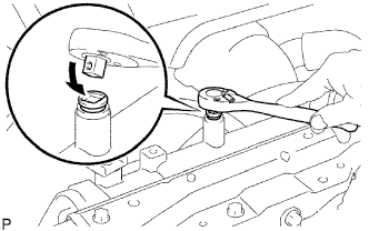
Drain the coolant by removing the reservoir cap and, using a wrench, remove the vent plug.
ENGINE ASSEMBLY (w/o Glow Plug Controller) > REMOVAL |
| 1. PRECAUTION |
| 2. DISCONNECT CABLE FROM NEGATIVE BATTERY TERMINAL |
| 3. REMOVE HOOD SUB-ASSEMBLY |
Disconnect the washer nozzle hose.
Remove the 4 bolts and hood.
| 4. REMOVE NO. 1 ENGINE UNDER COVER |
| 5. REMOVE NO. 2 ENGINE UNDER COVER |
| 6. DRAIN ENGINE OIL |
Remove the oil filler cap.
Remove the oil drain plug, and drain the engine oil from the oil pan.
| 7. DRAIN ENGINE COOLANT |
|
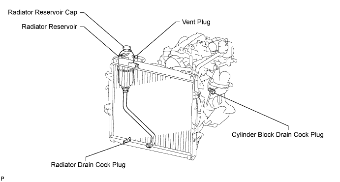
Drain the coolant by removing the reservoir cap and, using a wrench, remove the vent plug.
Loosen the cylinder block drain cock plug and the radiator drain cock plug.
| 8. DRAIN TRANSMISSION OIL (for Manual Transmission) |
Remove the drain plug and gasket to drain the oil.
Install a new gasket and the drain plug.
| 9. DRAIN TRANSMISSION FLUID (for Automatic Transmission) |
Remove the drain plug and gasket, and drain ATF.
Install a new gasket and the drain plug.
| 10. DRAIN POWER STEERING FLUID |
| 11. REMOVE BATTERY CLAMP SUB-ASSEMBLY |
Remove the bolt, nut and battery clamp.
| 12. REMOVE BATTERY |
| 13. REMOVE BATTERY TRAY |
| 14. REMOVE AIR CLEANER ASSEMBLY |
Disconnect the mass air flow meter connector.
Loosen the hose clamp.
Remove the 2 bolts and air cleaner.
| 15. REMOVE INTERCOOLER ASSEMBLY WITH INTAKE AIR CONNECTOR |
| 16. REMOVE RADIATOR ASSEMBLY |
| 17. REMOVE STARTER ASSEMBLY |
| 18. REMOVE FRONT EXHAUST PIPE ASSEMBLY |
| 19. REMOVE FRONT PROPELLER SHAFT ASSEMBLY |
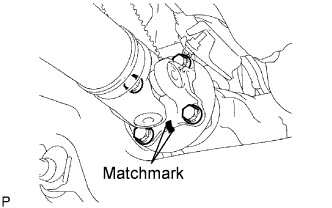 |
Place matchmarks on the propeller shaft flange and differential.
Remove the 4 nuts, 4 bolts and 4 washers, and disconnect the propeller shaft.
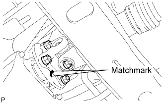 |
Place matchmarks on the propeller shaft flange and transfer flange.
Remove the 4 nuts, 4 washers and front propeller shaft.
| 20. REMOVE PROPELLER WITH CENTER BEARING SHAFT ASSEMBLY |
| 21. DISCONNECT HEATER HOSE |
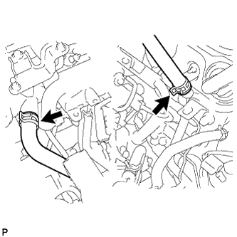 |
Disconnect the 2 heater hoses.
| 22. DISCONNECT PRESSURE FEED TUBE ASSEMBLY |
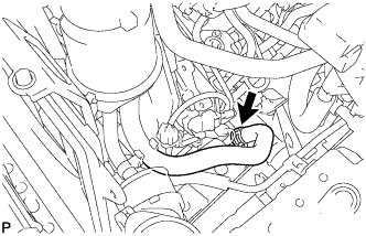 |
Disconnect the oil reservoir to pump hose.
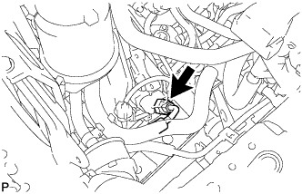 |
Disconnect the pressure feed tube.
| 23. DISCONNECT FUEL HOSE |
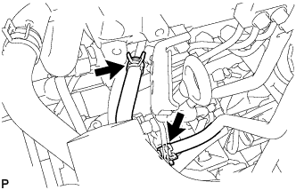 |
Disconnect the 2 fuel hoses.
| 24. DISCONNECT UNION TO CONNECTOR TUBE HOSE |
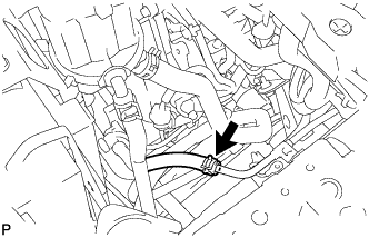 |
Disconnect the union to connector tube hose.
| 25. REMOVE GLOVE COMPARTMENT DOOR ASSEMBLY |
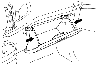 |
Slightly bend the upper part of the glove compartment door to release the 2 stoppers and open the glove compartment door until it is horizontal.
| *1 | Stopper |
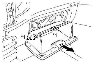 |
Pull the glove compartment door toward the rear of the vehicle to detach the 2 hinges and remove the glove compartment door.
| *1 | Hinge |
| 26. DISCONNECT WIRE HARNESS |
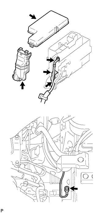 |
Remove the upper relay block cover.
Remove the side relay block cover.
Remove the nut and disconnect the engine room junction block wire.
Disconnect the 2 engine room junction block connectors.
Remove the bolt and disconnect the ground cable.
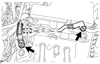 |
Remove the 2 nuts, detach the clamp and disconnect the wire harness.
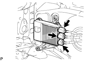 |
Disconnect the 3 injector driver connectors.
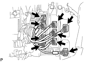 |
Disconnect the turbo motor driver connector.
Disconnect the 4WD control ECU connector.
for Automatic Transmission:
Disconnect the 3 TCM connectors.
Disconnect the 4 ECM connectors.
| 27. DISCONNECT COOLER COMPRESSOR ASSEMBLY |
Remove the 4 bolts and disconnect the cooler compressor.
| 28. REMOVE MANUAL TRANSMISSION ASSEMBLY (for Manual Transmission) |
| 29. REMOVE DRIVE PLATE AND TORQUE CONVERTER SETTING BOLT (for Automatic Transmission) |
| 30. REMOVE AUTOMATIC TRANSMISSION ASSEMBLY (for Automatic Transmission) |
| 31. REMOVE REAR NO. 1 ENGINE MOUNTING INSULATOR |
Remove the 4 bolts and rear No. 1 engine mounting insulator.
| 32. REMOVE CLUTCH COVER ASSEMBLY (for Manual Transmission) |
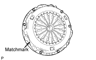 |
Place matchmarks on the clutch cover and flywheel.
Loosen each set bolt one turn at a time until spring tension is released.
Remove the 6 set bolts and pull off the clutch cover.
| 33. REMOVE CLUTCH DISC ASSEMBLY (for Manual Transmission) |
| 34. REMOVE FLYWHEEL SUB-ASSEMBLY (for Manual Transmission) |
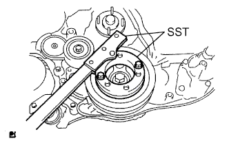 |
Using SST, hold the crankshaft pulley.
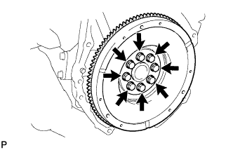 |
Remove the 8 bolts and flywheel.
| 35. REMOVE PUMP IMPELLER DRIVE PLATE (for Automatic Transmission) |
|
Using SST, hold the crankshaft pulley.
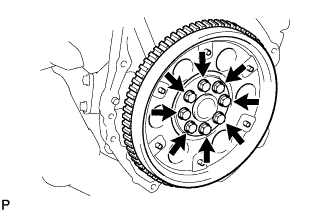 |
Remove the 8 bolts, rear drive plate spacer, pump impeller drive plate and flywheel.
| 36. REMOVE REAR END PLATE |
Remove the bolt and rear end plate.
| 37. INSTALL ENGINE HANGERS |
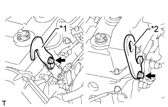 |
Install a No. 1 engine hanger and No. 2 engine hanger with 2 bolts as shown in the illustration.
| *1 | No. 1 Engine Hanger |
| *2 | No. 2 Engine Hanger |
| No. 1 Engine Hanger | 12284-30020 |
| No. 2 Engine Hanger | 12282-67030 |
| Bolt | 91552-81014 and 91642-81030 |
| 38. REMOVE ENGINE ASSEMBLY |
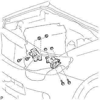 |
Attach an engine sling device and hang the engine with a chain block.
Remove the 4 bolts and 4 nuts.
Remove the engine by operating the engine sling device and chain block.
| 39. INSTALL ENGINE TO ENGINE STAND |
Install the engine to an engine stand with bolts.
Remove the 2 bolts and 2 engine hangers.
| 40. REMOVE ENGINE WIRE |
Remove the engine wire from the engine.
| 41. REMOVE FRONT ENGINE MOUNTING INSULATOR |
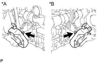 |
Remove the 2 nuts and 2 front engine mounting insulators.
| *A | RH Side |
| *B | LH Side |
| 42. REMOVE NO. 1 TIMING BELT COVER |
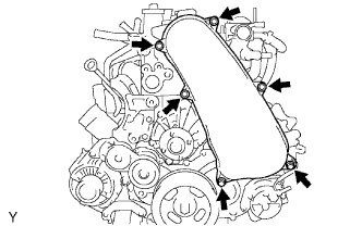 |
Remove the bolt and water hose clamp.
Remove the wire harness clamp.
Remove the 6 bolts and timing belt cover.
| 43. REMOVE TIMING BELT |
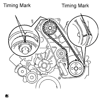 |
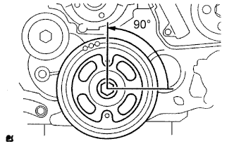
Turn the crankshaft clockwise and align the timing marks as shown in the illustration.
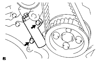 |
Uniformly loosen the 2 bolts and remove the timing belt tensioner.
Remove the timing belt.
Using a 10 mm hexagon wrench, remove the bolt, timing belt idler and washer.
| 44. REMOVE NO. 1 TIMING BELT IDLER SUB-ASSEMBLY |
| 45. REMOVE CRANKSHAFT PULLEY |
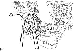 |
Using SST, hold the crankshaft pulley and loosen the pulley bolt.
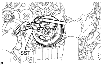 |
Using SST, remove the pulley bolt and crankshaft pulley.
| 46. REMOVE NO. 2 INTERCOOLER SUPPORT BRACKET |
Remove the 2 bolts and No. 2 intercooler support bracket.
| 47. REMOVE NO. 1 INTERCOOLER SUPPORT BRACKET |
Remove the 2 bolts and No. 1 intercooler support bracket.
| 48. REMOVE COMPRESSOR INLET ELBOW |
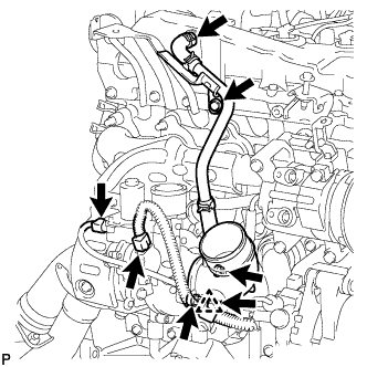 |
Remove the bolt from the ventilation pipe.
Move the clamp so that the hose can be disconnected.
Disconnect the ventilation pipe from the cylinder head cover.
Disconnect the 2 connectors from the turbocharger.
Remove the wire clamp's clip from the inlet elbow.
Remove the 2 nuts, inlet elbow and gasket.
| 49. REMOVE NO. 1 TURBO INSULATOR |
Remove the bolt and insulator.
| 50. REMOVE NO. 1 EXHAUST MANIFOLD HEAT INSULATOR |
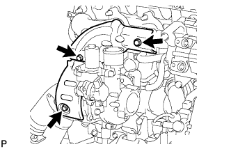 |
Remove the 2 bolts and heat insulator.
| 51. REMOVE NO. 1 TURBO WATER HOSE |
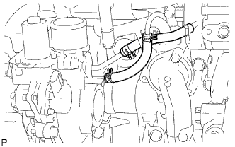 |
Move the 2 clamps and disconnect the 2 hoses.
| 52. REMOVE TURBINE OUTLET ELBOW |
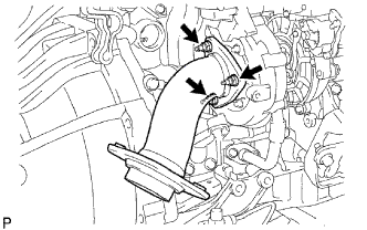 |
Remove the 3 nuts, outlet elbow and gasket.
| 53. REMOVE TURBOCHARGER STAY |
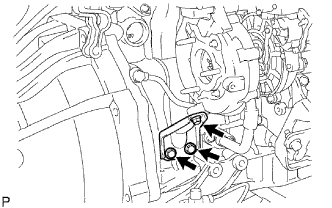 |
Remove the 3 bolts and stay.
| 54. DISCONNECT TURBO OIL INLET PIPE SUB-ASSEMBLY |
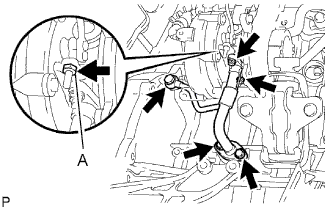 |
Remove the 2 bolts, 2 nuts, union bolt, inlet pipe and 3 gaskets.
| 55. REMOVE TURBOCHARGER SUB-ASSEMBLY |
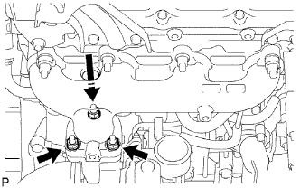 |
Remove the 3 nuts, turbocharger and gasket.
| 56. REMOVE EXHAUST MANIFOLD |
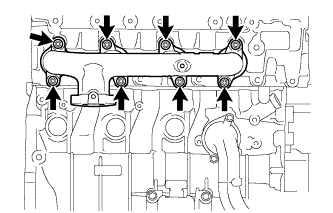 |
Remove the 8 nuts, 8 plate washers, 8 collars and exhaust manifold.
Remove the gasket.
| 57. REMOVE NO. 2 IDLE PULLEY ASSEMBLY |
Remove the bolt, pulley plate, No. 2 idle pulley and spacer.
| 58. REMOVE GENERATOR ASSEMBLY |
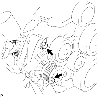 |
Remove the nut and generator wire.
Disconnect the generator connector.
Remove the 2 bolts and generator.
| 59. REMOVE GENERATOR BRACKET |
Remove the bolt and generator bracket.
| 60. REMOVE V-RIBBED BELT TENSIONER ASSEMBLY |
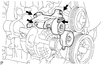 |
Remove the 4 bolts and V-ribbed belt tensioner.
| 61. REMOVE NO. 1 COMPRESSOR MOUNTING BRACKET |
Remove the 4 bolts and No. 1 compressor mounting bracket.
| 62. REMOVE WATER INLET |
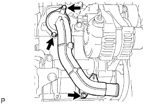 |
Remove the 3 bolts and inlet.
| 63. REMOVE THERMOSTAT |
| 64. REMOVE WATER OUTLET |
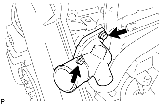 |
Remove the 2 bolts, water outlet and gasket.
| 65. REMOVE DIESEL THROTTLE BODY ASSEMBLY |
Disconnect the 2 connectors.
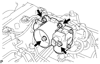 |
Remove the 2 bolts, 2 nuts, diesel throttle body and gasket.
| 66. REMOVE INTAKE MANIFOLD |
| 67. REMOVE GLOW PLUG ASSEMBLY |
| 68. REMOVE OIL FILTER SUB-ASSEMBLY |
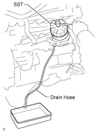 |
Using SST, remove the oil filter.
| 69. REMOVE FUEL INLET PIPE SUB-ASSEMBLY |
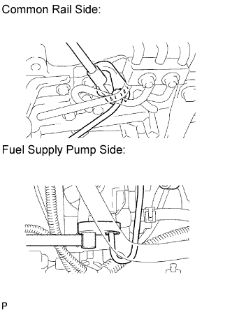 |
Using a 17 mm union nut wrench, loosen the union nuts and remove the fuel inlet pipe.
| 70. REMOVE COMMON RAIL ASSEMBLY |
Disconnect the 2 connectors.
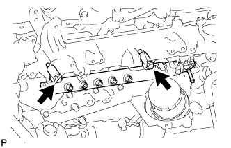 |
Remove the 2 bolts, common rail and No. 2 intake manifold insulator.
| 71. REMOVE FUEL SUPPLY PUMP ASSEMBLY |
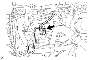 |
Remove the bolt and clamp.
Remove the bolt and oil dipstick guide.
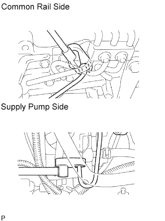 |
Using a 17 mm union nut wrench, loosen the union nuts and remove the fuel inlet pipe.
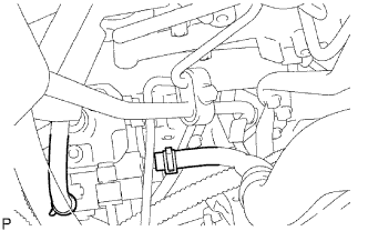 |
Disconnect the 2 fuel hoses.
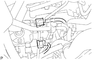 |
Disconnect the 2 connectors.
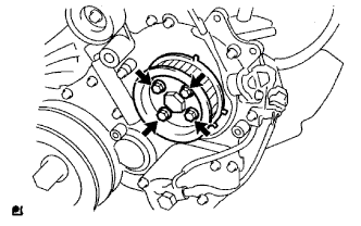 |
Remove the 4 bolts indicated by the arrows in the illustration.
Remove the No. 2 camshaft timing pulley flange and pump drive shaft pulley.
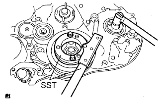 |
Remove the set nut and O-ring while holding the crankshaft pulley using SST.
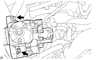 |
Loosen the 2 nuts.
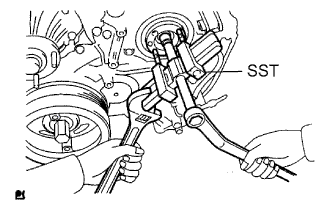 |
Using SST, disconnect the pump from the injection gear.
Remove the 2 nuts and pump.
Remove the O-ring.
| 72. REMOVE OIL COOLER COVER SUB-ASSEMBLY |
Disconnect the oil pressure switch connector and wire harness.
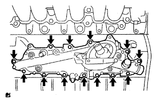 |
Remove the 13 bolts, 2 nuts and oil cooler cover.
| 73. REMOVE TIMING GEAR COVER INSULATOR (w/ EGR Cooler) |
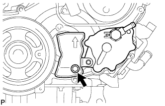 |
Remove the bolt and timing gear cover insulator.
| 74. REMOVE VACUUM PUMP ASSEMBLY |
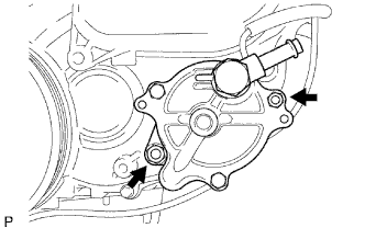 |
Remove the 2 nuts, vacuum pump and 2 O-rings.
| 75. REMOVE VANE PUMP ASSEMBLY |
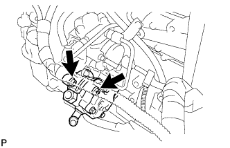 |
Remove the 2 nuts, vane pump and O-ring.
| 76. REMOVE CRANKSHAFT POSITION SENSOR |
Disconnect the crankshaft position sensor connector.
Detach the 3 clips, and the bolt and crankshaft position sensor.
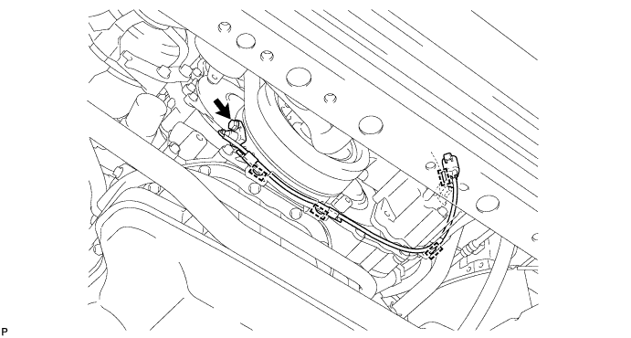
| 77. REMOVE CAMSHAFT POSITION SENSOR |
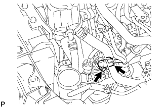 |
Disconnect the camshaft position sensor connector.
Remove the bolt and camshaft position sensor.
| 78. REMOVE ENGINE COOLANT TEMPERATURE SENSOR |
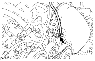 |
Disconnect the engine coolant temperature sensor connector.
Remove the engine coolant temperature sensor.
Remove the gasket from the engine coolant temperature sensor.
| 79. REMOVE FRONT NO. 1 ENGINE MOUNTING BRACKET RH |
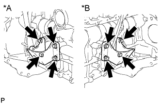 |
Remove the 4 bolts and front No. 1 engine mounting bracket.
| *A | RH Side |
| *B | LH Side |
| 80. REMOVE FRONT NO. 1 ENGINE MOUNTING BRACKET LH |
Remove the 4 bolts and front No. 1 engine mounting bracket.