RC60 / RC61 MANUAL TRANSMISSION / TRANSAXLE MANUAL TRANSMISSION ASSEMBLY REMOVAL
CAUTION / NOTICE / HINT
The necessary procedures (adjustment, calibration, initialization, or registration) that must be performed after parts are removed, installed, or replaced during the automatic transmission assembly removal/installation are shown below.
| Replacement Part or Procedure | Necessary Procedures | Effects/Inoperative when not Performed | Link |
|---|---|---|---|
| Battery terminal is disconnected/reconnected | Drive the vehicle until stop and start control is permitted (approximately 15 to 40 minutes) | Stop and start system | ( ) |
| Memorize steering angle neutral point | Pre-crash safety system | ()
|
- CAUTION:
- ·
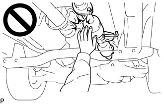
To prevent burns, do not touch the engine, exhaust pipe or other high temperature components while the engine is hot.
·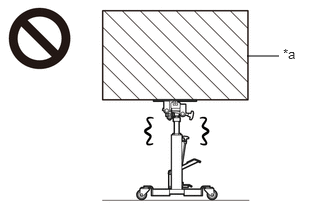 2.573,0.583 2.906,0.583 false 2.948,0.479 3.26,0.677 0.313,0.198 10 false *a
*a Object Exceeding Weight Limit of Transmission Jack
The manual transmission assembly is very heavy. Be sure to follow the procedure described in the repair manual, or the transmission jack may suddenly drop or a part may fall.
PROCEDURE

 1. PRECAUTION
- NOTICE:
-
After turning the ignition switch off, waiting time may be required before disconnecting the cable from the battery terminal. Therefore, make sure to read the disconnecting the cable from the battery terminal notice before proceeding with work.
-
Click hereGeneral>INTRODUCTION>REPAIR INSTRUCTION>PRECAUTION
28800
2.DISCONNECT CABLE FROM NEGATIVE BATTERY TERMINAL
- NOTICE:
-
When disconnecting the cable, some systems need to be initialized after the cable is reconnected.
-
Click hereGeneral>INTRODUCTION>REPAIR INSTRUCTION>INITIALIZATION
58810J
3.REMOVE CONSOLE BOX ASSEMBLY (w/ Console Box Lid)
58811A
4.REMOVE FRONT CONSOLE BOX (w/o Console Box Lid)
58280A
5.REMOVE SHIFT LEVER BOOT ASSEMBLY
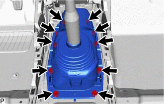
Remove the 6 screws, 4 clips and shift lever boot assembly.
33530F
6.REMOVE FLOOR SHIFT SHIFT LEVER ASSEMBLY
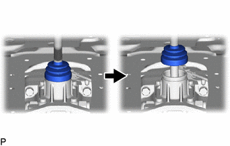
Detach the shift lever cap boot from the manual transmission.
Cover the shift lever cap with a cloth.
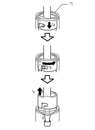
| *1 | Shift Lever Cap |
| *a | Press Down |
| *b | Counterclockwise |
| *c | Pull out |
While pressing down on the shift lever cap, turn it counterclockwise, and then pull to remove the shift lever.
33548F
7.REMOVE NO. 1 FLOOR SHIFT BUSH
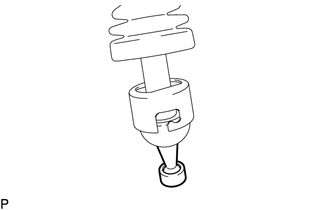
Remove the No. 1 floor shift bush from the floor shift shift lever assembly.
8.DRAIN MANUAL TRANSMISSION OIL
51410
9.REMOVE NO. 1 ENGINE UNDER COVER ASSEMBLY
51442
10.REMOVE NO. 2 ENGINE UNDER COVER
17410
11.REMOVE FRONT EXHAUST PIPE ASSEMBLY (for 1GD-FTV)
17410
12.REMOVE FRONT EXHAUST PIPE ASSEMBLY (for 2GD-FTV)
17410
13.REMOVE FRONT EXHAUST PIPE ASSEMBLY (for 2KD-FTV)
77801A
14.REMOVE UREA TANK SUB-ASSEMBLY (w/ Urea SCR System)
28100
15.REMOVE STARTER ASSEMBLY (for 1GD-FTV)
for 2.0 kW Type:
Click hereEngine / Hybrid System>1GD-FTV STARTING>STARTER(for 2.0 kW Type)>REMOVAL
for 2.2 kW Type:
Click hereEngine / Hybrid System>1GD-FTV STARTING>STARTER(for 2.2 kW Type)>REMOVAL
for BOSCH Made:
Click hereEngine / Hybrid System>1GD-FTV STARTING>STARTER(for BOSCH Made)>REMOVAL
28100
16.REMOVE STARTER ASSEMBLY (for 2GD-FTV)
for 2.0 kW Type:
Click hereEngine / Hybrid System>2GD-FTV STARTING>STARTER(for 2.0 kW Type)>REMOVAL
for 2.2 kW Type:
Click hereEngine / Hybrid System>2GD-FTV STARTING>STARTER(for 2.2 kW Type)>REMOVAL
for 2.7 kW Type:
Click hereEngine / Hybrid System>2GD-FTV STARTING>STARTER(for 2.7 kW Type)>REMOVAL
for BOSCH Made:
Click hereEngine / Hybrid System>2GD-FTV STARTING>STARTER(for BOSCH Made)>REMOVAL
w/ Stop and Start System:
Click hereEngine / Hybrid System>2GD-FTV STARTING>STARTER(w/ Stop And Start System)>REMOVAL
28100
17.REMOVE STARTER ASSEMBLY (for 2KD-FTV)
for 2.0 kW Type:
Click hereEngine / Hybrid System>2KD-FTV STARTING>STARTER(for 2.0 kW Type)>REMOVAL
for 2.2 kW Type:
Click hereEngine / Hybrid System>2KD-FTV STARTING>STARTER(for 2.2 kW Type)>REMOVAL
for BOSCH Made:
Click hereEngine / Hybrid System>2KD-FTV STARTING>STARTER(for BOSCH Made)>REMOVAL
12584
18.REMOVE NO. 4 CYLINDER BLOCK INSULATOR
Remove the No. 4 cylinder block insulator.
33119
19.REMOVE STIFFENER PLATE LH
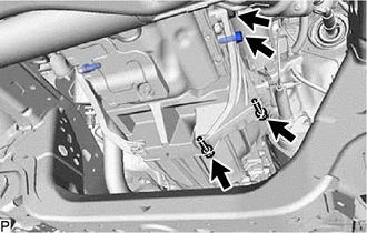
Remove the 4 bolts and stiffener plate LH.
33118
20.REMOVE STIFFENER PLATE RH
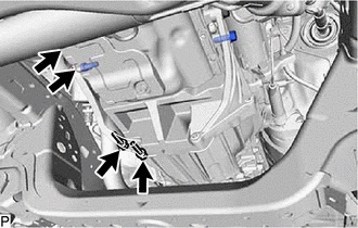
Remove the 4 bolts and stiffener plate RH.
37100
21.REMOVE PROPELLER SHAFT WITH CENTER BEARING ASSEMBLY
for TMT Made:
Click hereDrivetrain>DRIVE SHAFT / PROPELLER SHAFT>PROPELLER SHAFT ASSEMBLY(for TMT Made)>REMOVAL
for TSAM Made:
Click hereDrivetrain>DRIVE SHAFT / PROPELLER SHAFT>PROPELLER SHAFT ASSEMBLY(for TSAM Made)>REMOVAL
22.DISCONNECT GROUND CABLE
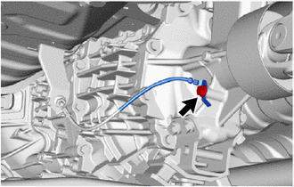
Remove the bolt and disconnect the ground cable.
23.SUPPORT MANUAL TRANSMISSION ASSEMBLY
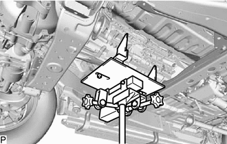
Support the manual transmission with a transmission jack.
- NOTICE:
- ·
Make sure the high transmission jack attachment is centered on the safety stand.
·Secure the part with a rope, attachment, etc.
51204
24.REMOVE NO. 3 FRAME CROSSMEMBER SUB-ASSEMBLY
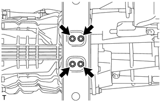
Remove the 4 bolts from the No. 3 frame crossmember sub-assembly.
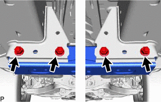
Remove the 4 nuts, 4 bolts and No. 3 frame crossmember sub-assembly.
12371A
25.REMOVE REAR ENGINE MOUNTING INSULATOR
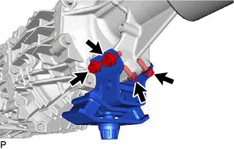
Remove the 4 bolts and rear engine mounting insulator from the manual transmission assembly.
26.DISCONNECT WIRE HARNESS
w/ Stop and Start System:
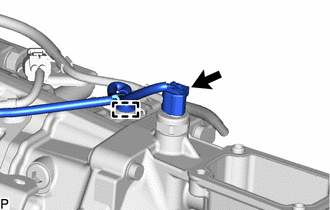
Detach the wire harness clamp and disconnect the neutral position switch conector.
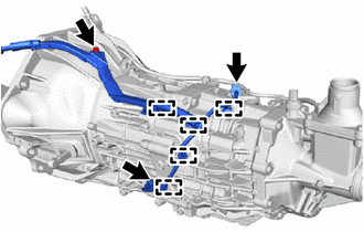
w/ Intelligent Manual Transmission Switch:
Detach the 5 wire harness clamps.
Remove the bolt.
Disconnect the 2 connectors and wire harness.
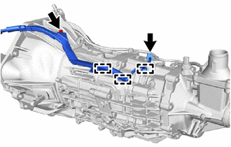
w/o Intelligent Manual Transmission Switch:
Detach the 3 wire harness clamps.
Remove the bolt.
Disconnect the connector and wire harness.
27.REMOVE MANUAL TRANSMISSION ASSEMBLY
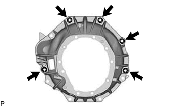
Remove the 5 bolts and manual transmission assembly.
- NOTICE:
-
As the manual transmission assembly is very heavy, be sure to support it securely.
33019C
28.REMOVE TRANSMISSION BREATHER SUB-ASSEMBLY
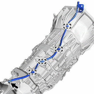
Detach the 4 breather hose clamps and bracket.
Remove the transmission breather sub-assembly from the control shift lever retainer sub-assembly.
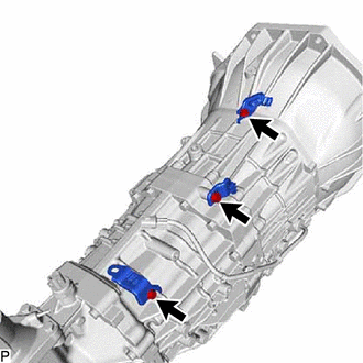
Remove the 3 bolts and 3 brackets.
29.REMOVE WIRING HARNESS CLAMP BRACKET
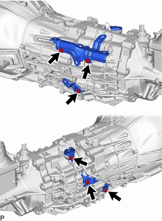
w/ Intelligent Manual Transmission Switch:
Remove the 6 bolts and 5 wiring harness clamp brackets.
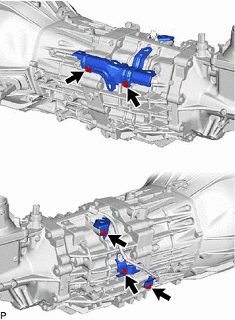
w/o Intelligent Manual Transmission Switch:
Remove the 5 bolts and 4 wiring harness clamp brackets.
33146
30.REMOVE EXTENSION HOUSING DUST DEFLECTOR
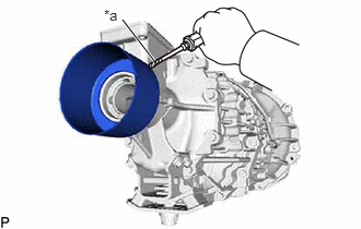
| *a | Protective Tape |
Using a screwdriver, pry out the extension housing dust deflector.
- NOTICE:
-
Be careful not to damage the extension housing sub-assembly.
- HINT:
-
Tape the screwdriver tip before use.