R150 MANUAL TRANSMISSION / TRANSAXLE MANUAL TRANSMISSION ASSEMBLY REMOVAL
PROCEDURE

 1. PRECAUTION
- NOTICE:
-
After turning the ignition switch off, waiting time may be required before disconnecting the cable from the battery terminal. Therefore, make sure to read the disconnecting the cable from the battery terminal notice before proceeding with work (See page General>INTRODUCTION>REPAIR INSTRUCTION>PRECAUTION)
2.DISCONNECT CABLE FROM NEGATIVE BATTERY TERMINAL
- NOTICE:
-
When disconnecting the cable, some systems need to be initialized after the cable is reconnected (See page General>INTRODUCTION>REPAIR INSTRUCTION>INITIALIZATION).
3.REMOVE CONSOLE BOX ASSEMBLY
4.REMOVE SHIFT LEVER BOOT ASSEMBLY
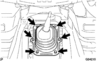
| *1 | Screw |
| *2 | Clip |
Remove the 4 screws, 2 clips and shift lever boot assembly.
5.REMOVE FLOOR SHIFT LEVER ASSEMBLY
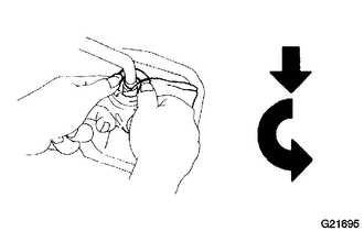
| *1 | Cloth |
| *a | Press down |
| *b | Rotate counterclockwise |
Cover the shift lever cap with a cloth.
Press down on the shift lever cap and rotate it counterclockwise to remove it.
Pull out the shift lever.
6.DRAIN MANUAL TRANSMISSION OIL
7.REMOVE NO. 2 FRAME CROSSMEMBER ASSEMBLY
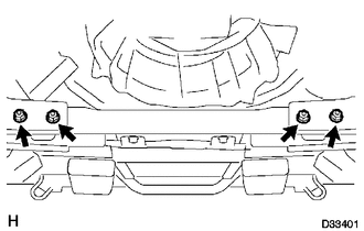
Remove the 4 bolts, 4 nuts and frame crossmember.
8.REMOVE PROPELLER WITH CENTER BEARING SHAFT ASSEMBLY
9.REMOVE FRONT EXHAUST PIPE ASSEMBLY
10.DISCONNECT WIRE HARNESS
Disconnect the back-up light switch connector and speedometer sensor connector.
11.DISCONNECT CLUTCH RELEASE CYLINDER ASSEMBLY
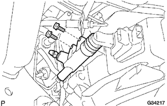
Remove the 2 bolts and disconnect the release cylinder assembly.
12.REMOVE STARTER ASSEMBLY
13.REMOVE NO. 3 FRAME CROSSMEMBER SUB-ASSEMBLY
Support the transmission rear side with a support stand.
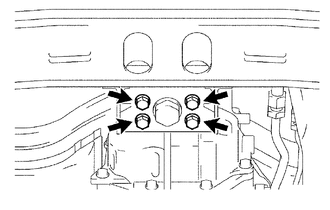
Remove the 4 set bolts of the rear No. 1 engine mounting insulator.
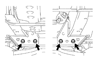
Remove the 4 bolts, 4 nuts and No. 3 frame crossmember sub-assembly.
14.REMOVE REAR NO. 1 ENGINE MOUNTING INSULATOR
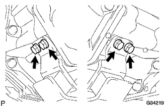
Remove the 4 bolts and mounting insulator.
15.REMOVE MANIFOLD STAY
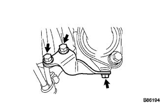
Remove the 3 bolts and exhaust manifold stay.
16.REMOVE MANUAL TRANSMISSION UNIT ASSEMBLY
Using a transmission jack, support the transmission.
Remove the support stand from the transmission.
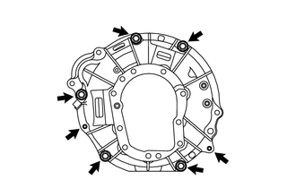
Remove the 7 bolts and transmission.