STEERING COLUMN STEERING COLUMN ASSEMBLY INSTALLATION
PROCEDURE

 1.INSTALL STEERING COLUMN ASSEMBLY
Install the steering column with the 3 bolts.
- Torque:
- 21 N*m (214 kgf*cm, 15 ft.*lbf)
2.INSTALL STEERING COLUMN HOLE COVER SUB-ASSEMBLY
Install the cover with the 3 bolts.
- Torque:
- 5.0 N*m (51 kgf*cm, 44 in.*lbf)
3.CONNECT CONNECTOR
Connect the connectors and attach the wire harness clamps.
4.CONNECT STEERING SLIDING YOKE
5.INSTALL LOWER INSTRUMENT CLUSTER FINISH PANEL
6.INSTALL COMBINATION SWITCH ASSEMBLY WITH SPIRAL CABLE SUB-ASSEMBLY
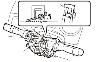
| *1 | Clamp |
| *2 | Claw |
Using pliers, pinch the clamp and attach the claw to install the combination switch assembly with spiral cable sub-assembly to the steering column assembly.
Connect the connectors to the combination switch assembly with spiral cable sub-assembly.
7.INSTALL STEERING COLUMN UPPER COVER
Attach the claw to install the upper cover.
8.INSTALL STEERING COLUMN LOWER COVER
Install the lower cover with the 3 screws.
9.INSTALL STEERING WHEEL ASSEMBLY
10.PLACE FRONT WHEELS FACING STRAIGHT AHEAD
11.CONNECT CABLE TO NEGATIVE BATTERY TERMINAL
- NOTICE:
-
When disconnecting the cable, some systems need to be initialized after the cable is reconnected (See page General>INTRODUCTION>REPAIR INSTRUCTION>INITIALIZATION).
12.CHECK SRS WARNING LIGHT