2013-2015 Land Cruiser Prado · Service Manual Engine / Hybrid System

REMOVAL

Removal / installation · Vehicles built from Aug 2014

Versions by build date: Aug 2013 – Jul 2014 from Aug 2014

NOTICE:
  1. When replacing the injectors (including shuffling the injectors between the cylinders), common rail or cylinder head, it is necessary to replace the injection pipes with new ones.
  2. When replacing the fuel supply pump, common rail, cylinder block, cylinder head, cylinder head gasket or timing gear case, it is necessary to replace the fuel inlet pipe with a new one.


1. DISCONNECT CABLE FROM NEGATIVE BATTERY TERMINAL

NOTICE:
  1. After turning the ignition switch off, waiting time may be required before disconnecting the cable from the battery terminal. Therefore, make sure to read the disconnecting the cable from the battery terminal notice before proceeding with work (Click here).
  2. When disconnecting the cable, some systems need to be initialized after the cable is reconnected (Click here).


2. DRAIN ENGINE OIL
  1. Remove the oil filler cap.

  1. Remove the oil pan drain plug and gasket, and then drain the engine oil into a container.

  1. Wipe the oil pan and drain plug.

  1. Install a new gasket and the oil pan drain plug.

    Torque:
    34 N*m{ 347 kgf*cm , 25 ft.*lbf }


3. REMOVE FRONT BUMPER LOWER COVER
  1. Remove the clip, 5 bolts and front bumper lower cover.


4. REMOVE NO. 1 ENGINE UNDER COVER SUB-ASSEMBLY
  1. Remove the 4 bolts and No. 1 engine under cover.


5. DRAIN ENGINE COOLANT

CAUTION:
Do not remove the radiator reservoir cap while the engine and radiator are still hot. Pressurized, hot engine coolant and steam may be released and cause serious burns.

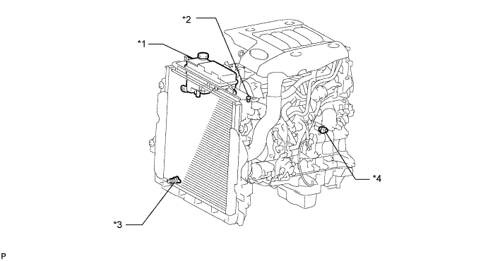
  1. Loosen the radiator drain cock plug.

    HINT:
    Collect the coolant in a container and dispose of it according to the regulations in your area.

  1. A218364
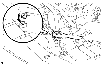
    Drain the coolant by removing the reservoir cap and, using a wrench, remove the vent plug.

  1. Loosen the cylinder block drain cock plug.

    A245857E01

    Text in Illustration 
    *1
    Radiator Reservoir
    *2
    Vent Plug
    *3
    Radiator Drain Cock Plug
    *4
    Cylinder Block Drain Cock Plug


6. REMOVE ENGINE ASSEMBLY
(Click here)

7. INSTALL ENGINE TO ENGINE STAND

8. REMOVE TIMING BELT
(Click here)

9. REMOVE ELECTRIC EGR CONTROL VALVE ASSEMBLY
(Click here)

10. REMOVE FUEL SUPPLY PUMP ASSEMBLY
(Click here)

11. REMOVE INJECTOR ASSEMBLY
(Click here)

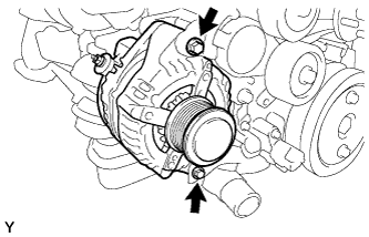
12. REMOVE GENERATOR ASSEMBLY

  1. A239368
    Remove the 2 bolts and generator.


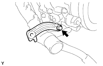
13. REMOVE GENERATOR BRACKET

  1. A239369
    Remove the bolt and generator bracket.


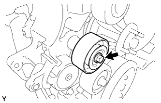
14. REMOVE NO. 2 IDLE PULLEY ASSEMBLY (w/ Air Conditioning System)

  1. A239370
    Remove the bolt, pulley plate, No. 2 idle pulley and spacer.


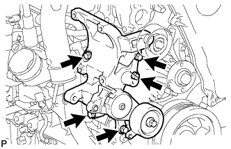
15. REMOVE NO. 1 COMPRESSOR MOUNTING BRACKET

  1. A244867
    Remove the 5 bolts and No. 1 compressor mounting bracket.


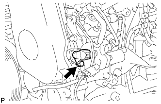
16. REMOVE CAMSHAFT POSITION SENSOR

  1. A224125
    Remove the bolt and camshaft position sensor.


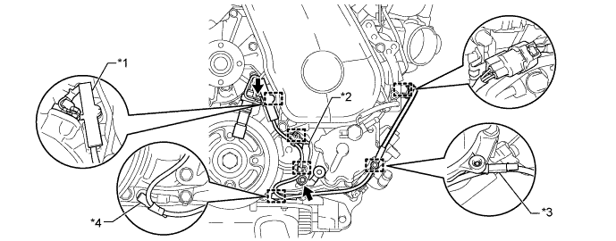
17. REMOVE CRANKSHAFT POSITION SENSOR
  1. Detach the 2 wire harness clamps (A, B).

  1. Disconnect the crankshaft position sensor connector.

  1. Detach the crankshaft position sensor connector from the No. 1 vacuum transmitting pipe.

  1. Remove the clamp.

    NOTICE:
    1. Make sure that no portion of the clamp remains in the clamp installation hole. If there is any portion of the clamp remaining, remove it.
    2. Do not reuse the clamp.

  1. Remove the bolt and bracket (clamp).

  1. Remove the bolt and crankshaft position sensor.

  1. Detach the 2 wire harness clamps from the bracket (clamp).

    A307963E01

    Text in Illustration 
    *1
    Clamp
    *2
    Bracket (Clamp)
    *3
    Wire Harness Clamps (A)
    *4
    Wire Harness Clamps (B)


18. REMOVE OIL PRESSURE SWITCHING VALVE ASSEMBLY

  1. A239379
    Remove the bolt and oil pressure switching valve.


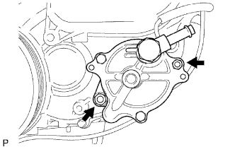
19. REMOVE VACUUM PUMP ASSEMBLY
  1. Remove the bolt and bracket.

  1. A098930E01
    Remove the 2 nuts, vacuum pump and 2 O-rings.


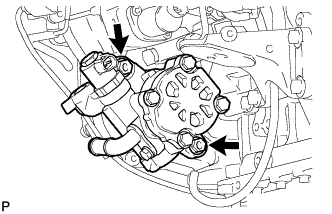
20. REMOVE VANE PUMP ASSEMBLY

  1. A224124
    Remove the 2 nuts, vane pump and O-ring.


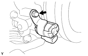
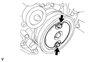
21. REMOVE CRANKSHAFT PULLEY COVER

  1. A239358
    Remove the 2 bolts and crankshaft pulley cover.


22. REMOVE CRANKSHAFT PULLEY

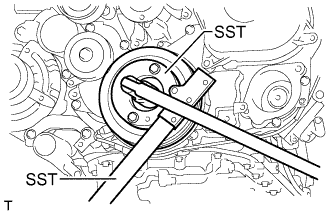
  1. A225341E01
    Using SST, hold the crankshaft pulley and loosen the pulley bolt.
    SST
    09213-58014  
    09330-00021  

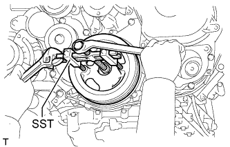
  1. A225342E01
    Using SST, remove the pulley bolt and crankshaft pulley.
    SST
    09950-50013   (09951-05010, 09952-05010, 09953-05020, 09954-05021)


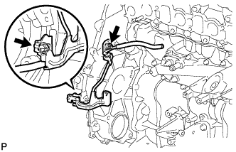
23. REMOVE NO. 1 VACUUM TRANSMITTING PIPE SUB-ASSEMBLY

  1. A239383
    Remove the bolt, nut and No. 1 vacuum transmitting pipe.


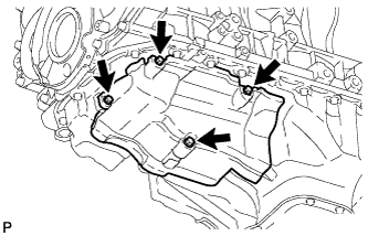
24. REMOVE NO. 1 OIL PAN COVER SUB-ASSEMBLY

  1. A224144
    Remove the 4 bolts and No. 1 oil pan cover.


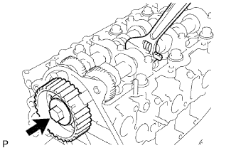
25. REMOVE CAMSHAFT TIMING PULLEY

  1. A060182E01
    Remove the bolt of the camshaft timing pulley while holding the camshaft with a wrench.

    NOTICE:
    Make sure the timing belt is not installed when removing the bolt of camshaft timing pulley.

  1. Remove the camshaft timing pulley.


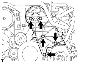
26. REMOVE NO. 2 TIMING BELT COVER

  1. A225464
    Remove the 4 bolts, nut and No. 2 timing belt cover.


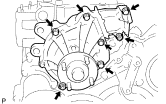
27. REMOVE WATER PUMP ASSEMBLY

  1. A225339
    Remove the 5 bolts, 2 nuts, water pump and gasket.


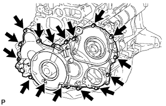
28. REMOVE TIMING GEAR COVER

NOTICE:
As the fuel supply pump is not installed, the injection gear is loose inside the timing gear case. Do not allow the injection gear to fall.

HINT:
To prevent the injection gear from falling, temporarily install the fuel supply pump.

  1. A239293
    Remove the 14 bolts and 2 nuts.

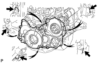
  1. A239294
    Pry the timing gear cover at the locations shown in the illustration and remove the timing gear cover.

    NOTICE:
    Be careful not to drop the injection gear.

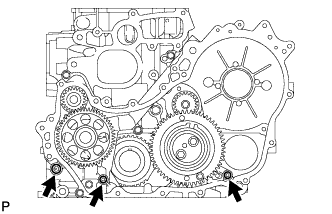
  1. A239295
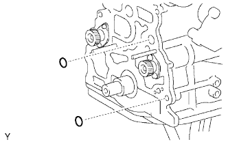
    Remove the 3 O-rings from the timing gear case.


29. REMOVE INJECTION GEAR

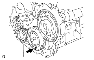
  1. A222329
    Secure the No. 2 idle sub gear to the No. 1 idle gear with a service bolt.

    Torque:
    8.0 N*m{ 82 kgf*cm , 71 in.*lbf }

    NOTICE:
    If the bolt hole of the No. 2 idle sub gear is not aligned with the bolt hole of the No. 1 idle gear, rotate the crankshaft counterclockwise to align the bolt holes. Then install the service bolt.

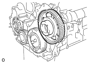
  1. A222330
    Remove the injection gear.


30. REMOVE NO. 1 CRANKSHAFT POSITION SENSOR PLATE

  1. A239296
    Remove the No. 1 crankshaft position sensor plate.


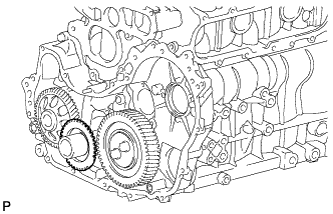
31. REMOVE CRANKSHAFT TIMING GEAR

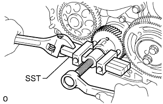
  1. A222332E01
    Using SST, remove the crankshaft timing gear.
    SST
    09950-50013   (09951-05010, 09952-05010, 09953-05010, 09954-05021)


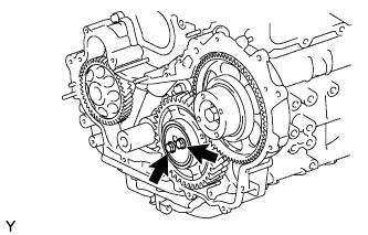
32. REMOVE IDLE GEAR THRUST PLATE

  1. A238857
    Remove the 2 bolts and idle gear thrust plate.

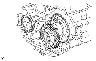
33. REMOVE NO. 1 IDLE GEAR

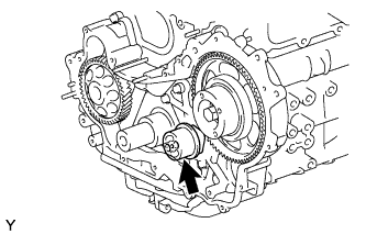
  1. A238858
    Remove the No. 1 idle gear together with the No. 2 idle sub gear.


34. REMOVE NO. 1 IDLE GEAR SHAFT

  1. A238859
    Remove the No. 1 idle gear shaft.


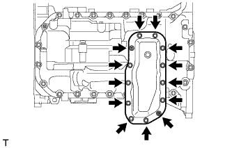
35. REMOVE NO. 2 OIL PAN SUB-ASSEMBLY

  1. A225306
    Remove the 11 bolts and 2 nuts.

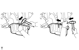
  1. A225310
    Insert the blade of an oil pan seal cutter between the oil pans. Cut through the applied sealer and remove the No. 2 oil pan.


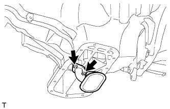
36. REMOVE OIL STRAINER SUB-ASSEMBLY

  1. A228657
    Remove the 2 nuts, oil strainer and gasket.


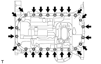
37. REMOVE OIL PAN SUB-ASSEMBLY

  1. A225307
    Remove the 22 bolts and 2 nuts.

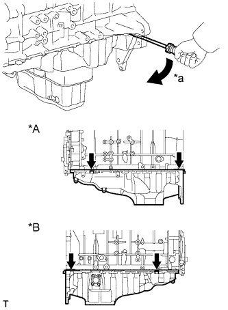
  1. A225311E02
    Using a screwdriver, remove the oil pan by prying between the oil pan and cylinder block as shown in the illustration.
    Text in Illustration 
    *A
    LH Side
    *B
    RH Side
    *a
    Pry

    NOTICE:
    Be careful not to damage the contact surfaces of the cylinder block and oil pan.

    HINT:
    Tape the screwdriver tip before use.
  1. A225308
    Remove the gasket.


38. REMOVE TIMING GEAR CASE ASSEMBLY

  1. A239298
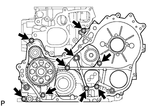
    Remove the union bolt and 8 bolts.

  1. A239299
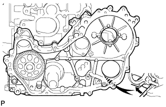
    Pry the timing gear case at the location shown in the illustration and remove the gear case and gasket.

  1. A069840E03
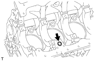
    Remove the 2 O-rings.

← REMOVAL (Aug 2013 – Jul 2014)DISASSEMBLY (from Aug 2013) →